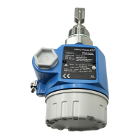
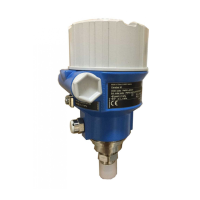
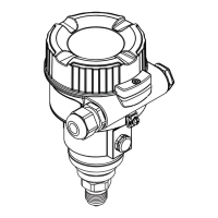
Gammapilot M
Endress+Hauser 15
Method for device parameterization
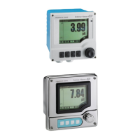
The device can be operated using the display FHX40, HART Communicator DXR375 or FieldCare
©
.
To configure the operating parameters and to operate the Gammapilot M, please proceed in accordance with
the Operating Instructions BA00236F/00/EN and the description of the device functions for point level
detection BA00287F/00/EN.
During calibration, a log must be kept to document the configuration values (see "Appendix" → ä 19).
"
Caution!
Following calibration, the Gammapilot M must be locked in order to activate the safety functions.
The Gammapilot M may be operated in safety-related applications only when it is in locked mode.
Locking procedure:
"
Caution!
If one of the parameters displayed does not correspond to the values logged during calibration, or if the
character string (step 4) is not displayed correctly, this parameter must be registered as not valid.
The Gammapilot M then automatically cancels the locking procedure. The status of the Gammapilot M is then
"unlocked".
Calibration can then be repeated.
If this is not successful, the device must not be used for safety-related applications.
Step Description Parameter
displayed
1 For this, please select the function "Safety locking (S22)" in the function group "Safety
settings (S2)".
Once the selection has been confirmed, an output current of ≤ 3 mA is output immediately.
2 Enter individual 4-digit password.
3 Confirmation of output current ≤ 3.0 mA. Verification of output current using measurement [Iout ≤ 3 mA]
4 The following character string appears
This character string is used to test the transmission of data to the operator device.
If the display is not correct, there is an error in the Gammapilot M or in the operator device.
Compare calibration values and configuration values with the calibration log and confirm
individually:
5 Background pulse rate [Backg: _ _ _ cps]
6 "Covered" calibration point
"Free" calibration point
[Covered: _ _ _ cps]
[Free: _ _ _ cps]
7 Isotope (
137
Cs or
60
Co)
Beam type (standard or modulated)
[Source: _ _ _ ]
[Beam: _ _ _ ]
8 Time response (default value 10 s if "modulated" beam type was selected)
Output damping
[GammaHld: _ _ _ s]
[Integr.: _ _ _ s]
9 Current date
Calibration date
[Pres.: _ _ _ ]
[Calib: _ _ _ ]
10 Detector length (measurement length in mm) [ _ _ _ mm]
11 Once the calibration values have been checked, the password must be confirmed once again
to complete the safety-related locking procedure.
Once it has been successfully locked, the device switches to measuring mode after a
diagnosis phase.
[ _ _ _ _ ]
12 A test must then be carried out to verify whether the Gammapilot M is actually locked.
This is done by monitoring the output current. Following an interval of approx. 2 minutes,
the current increases by approx. 1.6 mA for 15 seconds (see also Chapter
"Safety function" Section "Electronic partial stroke test"). This signal change indicates
that the Gammapilot M is locked.
If there is no signal change, there was an error in the transmission of data for the
confirmation. In this case, the operator device should be replaced and the locking procedure
repeated.
0123456789 . -

 Loading...


