Gammapilot M
14 Endress+Hauser
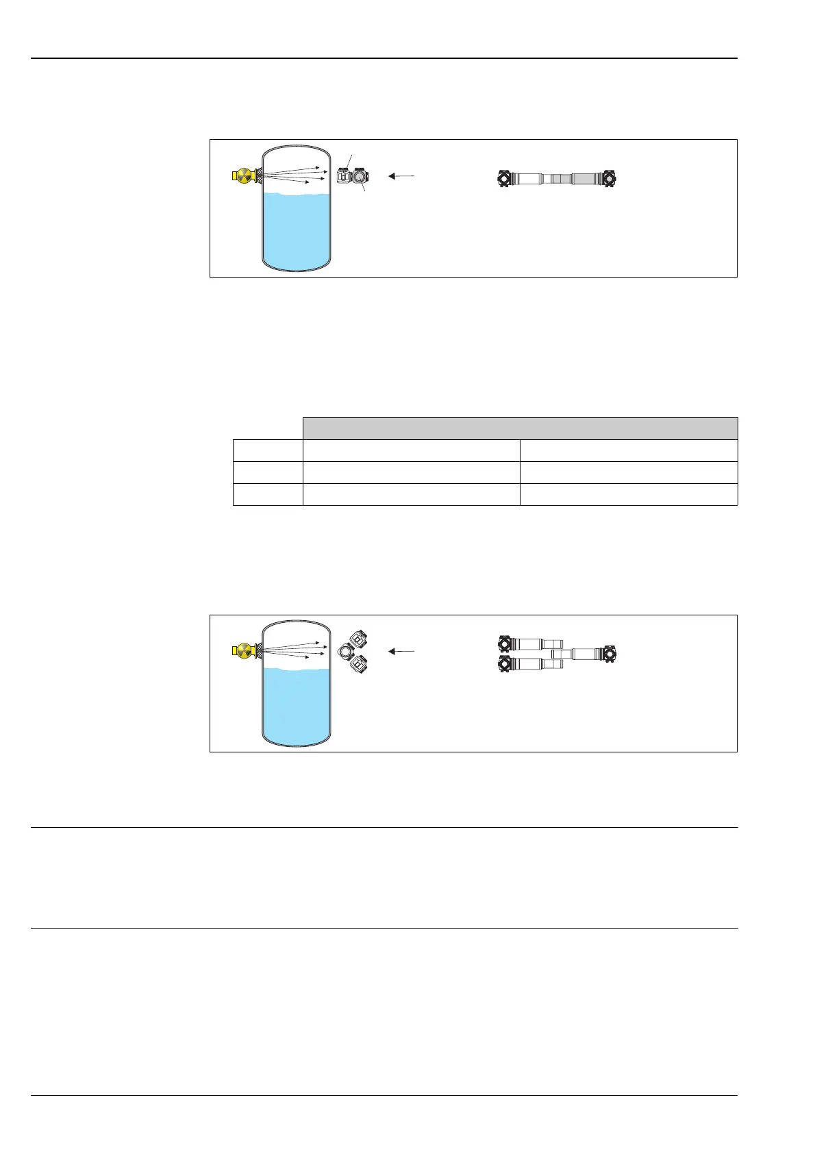
Installation with 1oo2 voting and detectors arranged horizontally beside one other:
SD230en10
!
Note!
• Due to the limited beam path geometry, this detector arrangement can be advantageous for small container
diameters.
• The Gammapilot M close to the tank (detector A) partially screens the Gammapilot M facing away from the
tank (detector B). This must be taken into consideration when planning the activity of the source.
The following table provides approximate information on the absorption:
Where necessary, the absorption can be partially compensated if 200 mm is used as the measuring length for
detector A and 400 mm for detector B.
Installation with 2oo3 voting in preferred arrangement:
SD230xx11
!
Note!
The position of the upper detector determines the most unfavorable switch point.
Operation
!
Note!
The term calibration, which is often used in the context of radiometric measuring systems, refers to the
calibration process of the measuring point installed in the system. The measuring point comprises a detector, a
radiation source and, if necessary, a modulator.
Calibrating the measuring
point
Once the basic settings (mode of operation, measurement method, date, type of radiation, source of radiation,
output damping) have been made, the actual calibration is performed. To ensure that the Gammapilot M can
compensate correctly for background radiation, the background calibration must always be performed first.
This is followed by empty and full calibration, in no particular order.
!
Note!
Once calibration has been completed, the Gammapilot M is operational and can be used in non-safety-related
applications.
For use in safety-related applications, the device must be locked in order to activate the safety functions
(see "Method for device parameterization" → ä 15).
X
X
Detector A
Detector B
Percentage pulse rate available at detector B
Source Detector without water cooling Detector with water cooling
137
Cs approx. 60 % approx. 36 %
60
Co approx. 70 % approx. 48 %
X
X
 Loading...


