EasyManua.ls Logo

Endress+Hauser Levelflex FMP51 - User Manual

Endress+Hauser Levelflex FMP51
250 pages
Print Icon
To Next Page IconTo Next Page
Loading...
Products Solutions Services
Operating Instructions
Levelflex FMP51, FMP52, FMP54
FOUNDATION Fieldbus
Guided wave radar
BA01052F/00/EN/04.16
71344062
01.01.zz (Device firmware)

Table of Contents

Other manuals for Endress+Hauser Levelflex FMP51

Questions and Answers

  • J
    jwilsonAug 23, 2025
    How to correct wrong slope of the level in the entire measuring range in Endress+Hauser Levelflex FMP51 Measuring Instruments?
    • J
      Joel JonesAug 25, 2025
      The wrong slope of the level in the entire measuring range could be caused by the wrong tank type being selected. To fix this, set the Tank type parameter correctly.
  • N
    Nicole CannonSep 1, 2025
    Why CDI communication is not working on Endress+Hauser Radar?
    • V
      Valerie ChambersSep 1, 2025
      If CDI communication does not work with your Endress+Hauser Radar, the COM port setting on your computer may be incorrect. Check the COM port setting and change it if necessary.
  • R
    Richard ArnoldSep 1, 2025
    What to do if parameter duplication is not working on Endress+Hauser Radar?
    • M
      Morgan HallSep 2, 2025
      If the duplication of parameters via display from one device to another is not working on your Endress+Hauser Radar and only the 'Save' and 'Cancel' options are available, it could be because the display with backup is not properly detected if a data backup was not carried out on the new device previously. Connect the display (with backup) and restart the device.
  • D
    dianacruzSep 2, 2025
    How to fix the wrong measured value on Endress+Hauser Measuring Instruments?
    • V
      Valerie ParkerSep 3, 2025
      A likely cause is a calibration error. To resolve this, check the Empty calibration parameter and adjust it if necessary. Also, check the Full calibration parameter and adjust it if needed. Finally, check the linearization and adjust it as necessary.
  • M
    Mr. Robert AlvarezSep 3, 2025
    What to do if there is no change of the measured value when emptying/filling the tank in Endress+Hauser Levelflex FMP51?
    • T
      Teresa FisherSep 3, 2025
      This issue may arise if an interference echo affects the measurement. To address it, perform mapping (interference echo suppression).
  • C
    Christian MorrisSep 4, 2025
    Why Endress+Hauser Levelflex FMP51 Measuring Instruments display a level when the tank is empty?
    • S
      strongleeSep 4, 2025
      The device may display a level even when the tank is empty due to an incorrect probe length. To solve this, carry out a probe length correction. Another possible cause is interference echo. In this case, carry out mapping over the entire probe when the tank is empty.
  • P
    pmendezSep 5, 2025
    What to do if diagnostic event F941 or S941 'Echo lost' appears on Endress+Hauser Measuring Instruments?
    • J
      Joseph RogersSep 5, 2025
      If the diagnostic event 'Echo lost' appears, it could be due to an echo threshold that is too high. To resolve this, check the Medium group parameter. If necessary, select a more detailed setting in the Medium property parameter. Another possible reason is that the level echo is suppressed. In this case, delete the suppression and, if necessary, record it again.
  • B
    Brianna AndersonSep 5, 2025
    Why the measured values for the interface and the total level are identical in Endress+Hauser Levelflex FMP51?
    • B
      burgessmicheleSep 5, 2025
      The measured values for the interface and the total level can be identical if the echo threshold for the total level is too high due to a wrong dielectric constant. To solve this, enter the correct dielectric constant (DC value) of the upper medium.
  • J
    Joanne BerrySep 6, 2025
    What causes the measured interface level to jump to higher values during draining when 'flooded' is selected in 'Tank level' on Endress+Hauser Levelflex FMP51?
    • W
      Walter HancockSep 6, 2025
      If, when 'flooded' is selected in 'Tank level', the measured interface level jumps to higher values during draining operations, a possible cause is that the total level is detected outside the upper blocking distance. To address this, increase the blocking distance. Alternatively, select 'Tank level' = 'Partially filled'.

Summary

Important Document Information

Document Function and Symbols

Explains the purpose of the operating instructions and defines safety, electrical, tool, and graphic symbols.

Supplementary Documentation

Lists related documents like Technical Information, Brief Operating Instructions, and parameter descriptions.

Basic Safety Instructions

Personnel, Designated Use, and Workplace Safety

Outlines requirements for personnel, designated applications, and workplace safety protocols.

Operational and Product Safety

Covers operational safety, unauthorized modifications, repairs, and product safety certifications (CE, EAC).

Product Description

Product Design and Components

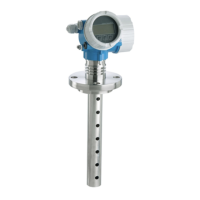
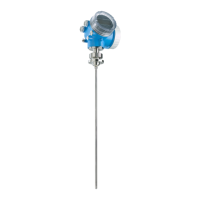
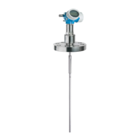
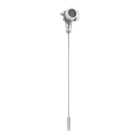
Details the Levelflex FMP51/FMP52/FMP54/FMP55 design, including housing and probe types.

Registered Trademarks

Lists registered trademarks used in the document, such as FOUNDATION Fieldbus and VITON.

Incoming Acceptance and Product Identification

Incoming Acceptance Checks

Details steps for checking delivery notes, goods condition, and nameplate data.

Product Identification Methods

Explains how to identify the measuring device using nameplate, order code, W@M Device Viewer, or Operations App.

Storage, Transport

Storage Conditions

Specifies the permitted storage temperature range and the use of original packaging.

Transport to Measuring Point

Provides guidelines for safe transport, including handling warnings and fastening points.

Mounting

Mounting Requirements and Positions

Details mounting distances, suitable positions, and additional conditions for proper installation.

Mounting the Device with Thread and Flange

Explains how to mount the device using threaded connections or flanges, including torque specifications.

Mounting the Sensor remote Version

Describes the installation of devices with a remote sensor, including cable connection and bending radius.

Post-installation Check

Lists checks to perform after installation to ensure the device is undamaged and correctly installed.

Electrical Connection

Connection Conditions and Terminal Assignment

Details terminal assignments for FOUNDATION Fieldbus, including overvoltage protection options.

Cable Specification and Plug Connectors

Covers cable specifications, plug connectors (M12, 7/8"), and connection examples.

Power Supply and Overvoltage Protection

Explains power supply requirements for FOUNDATION Fieldbus and details integrated/external overvoltage protection.

Operation Options

Local Operation Modes

Describes local operation using pushbuttons or touch control and its additional functionalities.

Remote Operation

Explains remote operation via FOUNDATION Fieldbus system architecture and service interface (CDI).

Structure and Function of the Operating Menu

Details the operating menu structure, user roles, access authorization, and write protection.

Display and Operating Module Functions

Covers display appearance, symbols, status signals, locking states, and operating elements.

Integration into FOUNDATION Fieldbus Network

Device Description (DD) and Integration

Information on DD files, integration steps, and device identification/addressing in FF networks.

Block Model and Configuration

Explains the device's block structure, including Resource, Transducer, and Function Blocks.

Parameter Index Tables

Lists parameters for Setup, Advanced Setup, Display, Diagnostic, Expert, and Service Transducer Blocks.

Methods for Device Operation

Describes methods like Restart, Setup, Linearization, and Self Check for device operation.

Commissioning

Commissioning via Wizard

Guides users through initial setup using FieldCare or DeviceCare wizards.

Commissioning via Operating Menu

Details steps for installation checks, language settings, reference distance, and measurement configuration.

Configuration of Interface Measurement

Provides steps for configuring interface measurements, including tank level and DC value.

Configuration Management and Event Behavior

Covers saving/restoring configurations, managing events, and transmitting data.

Diagnostics and Troubleshooting

General Troubleshooting and Parametrization Errors

Addresses general errors like device response issues and parametrization errors for level/interface measurements.

Diagnostic Information on Local Display

Explains how diagnostic messages, status signals, and event texts are displayed and interpreted.

Event Logbook and Filtering

Covers viewing event history, filtering events by category, and understanding information events.

Maintenance

Exterior Cleaning

Provides instructions for cleaning the device exterior using appropriate cleaning agents.

Repairs

General Repair Information and Ex-Approved Devices

Covers repair concepts, spare parts, and specific procedures for Ex-approved devices.

Module and Device Replacement

Details the process for replacing electronics modules or the entire device and parameter download.

Accessories

Device-Specific Accessories

Lists accessories like weather protection covers, mounting brackets, and extension rods.

Communication-Specific Accessories

Details accessories for communication, such as Commubox FXA291 and Field Xpert devices.

System Components

Mentions system components like the Graphic Data Manager Memograph M for data management.

Operating Menu

Overview of Operating Menu (Display Module)

Provides a structured overview of the operating menu accessible via the device's display module.

Overview of Operating Menu (Operating Tool)

Maps out the operating menu structure accessible via external operating tools like FieldCare.

Setup Menu Parameters

Details parameters within the Setup menu, including operating mode, tank type, and calibration.

Diagnostics Menu Parameters

Covers parameters for diagnostics like actual, previous, and event logbook information.

Heartbeat Submenu

Explains the Heartbeat submenu for device diagnostics and monitoring application packages.

Endress+Hauser Levelflex FMP51 Specifications

General IconGeneral
Device TypeGuided radar level transmitter
ApplicationLevel measurement for liquids and solids
Measuring RangeUp to 30 m
Process Temperature-40 to 200 °C (-40 to 392 °F)
Process Pressure-1 to +40 bar (-14.5 to +580 psi)
Output Signal4-20 mA HART, PROFIBUS PA, FOUNDATION Fieldbus
Housing MaterialAluminum, Stainless steel
Probe TypeRod or cable
MaterialStainless steel, PTFE
Protection RatingIP66/IP67
ApprovalsATEX, IECEx, FM, CSA
Power Supply10.5 to 36 V DC

Related product manuals