Micropilot FMR20 HART
16 Endress+Hauser
Please note the limits for the diameter and length of the nozzle.
80 mm (3 in) antenna, installation inside nozzle
• D: min. 120 mm (4.72 in)
• L: max. 205 mm (8.07 in) + D × 4.5
80 mm (3 in) antenna, installation outside nozzle
• D: min. 80 mm (3 in)
• L: max. D × 4.5
40 mm (1.5 in) antenna, installation outside nozzle
• D: min. 40 mm (1.5 in)
• L: max. D × 1.5
40 mm (1.5 in) antenna, installation inside nozzle
• D: min. 80 mm (3 in)
• L: max. 140 mm (5.5 in) + D × 1.5
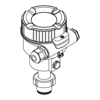
Device alignment for installation on a vessel
• Align the antenna vertically to the product surface.
• Align the eyelet with lug towards the vessel wall as well as possible.
A0028927
13 Device alignment for installation on a vessel
Beam angle
A0033201
14 Relationship between beam angle α, distance D and beamwidth diameter W
The beam angle is defined as the angle α, at which the power density of the radar waves reaches half
the value of the maximum power density (3 dB width). Microwaves are also emitted outside the
signal beam and can be reflected off interfering installations.

 Loading...