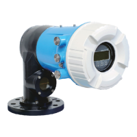
Operating menu Tankside Monitor NRF81
138 Endress+Hauser
"Analog I/O" submenu
There is a Analog I/O submenu for each Analog I/O module of the device. This
submenu refers to terminals 1 to 3 of this module (an analog input or output). For
terminals 4 to 8 (always an analog input) refer to → 132.
D
E
F
C
B
A
1
1
1
1 3
2
2 4
1
HR
CDI
WP
on
SIM
2
2
3
3
4
4
1
1
2
2
3
3
4
4
5
5
6
6
7
7
8
8
POWER
i
B
B1-3 B4-8
1 2 3 4 5 6 7 8
A0032464
45 Terminals for the "Analog I/O" submenu ("B1-3" or "C1-3", respectively)
Navigation Setup → Advanced setup → Input/output → Analog I/O
Operating mode
Navigation Setup → Advanced setup → Input/output → Analog I/O → Operating mode
Description Defines the operating mode of the analog I/O module.
Selection • Disabled
• 4..20mA input
• HART master+4..20mA input
• HART master
• 4..20mA output
• HART slave +4..20mA output
Factory setting Disabled
Additional information
Read access Operator
Write access Maintenance
Meaning of the options
Operating mode (→ 138) Direction of signal Type of signal
Disabled - -
4..20mA input Input from 1 external device Analog (4...20mA)
HART master+4..20mA input Input from 1 external device • Analog (4...20mA)
• HART
HART master Input from up to 6 external devices HART
 Loading...


