This document describes the Proline Promag W 300 PROFINET Electromagnetic flowmeter, an electromagnetic flowmeter designed for measuring the flow of liquids with a minimum conductivity of 5 µS/cm. Depending on the ordered version, it can also measure potentially explosive, flammable, poisonous, and oxidizing media.
Function Description
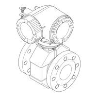
The device consists of a transmitter and a sensor, forming a compact mechanical unit. It operates on Faraday's law of magnetic induction to measure volume flow and electrical conductivity directly, and can calculate mass flow.
The device offers various operation options, including local operation via a display module, a computer with a web browser or operating tool (e.g., FieldCare, DeviceCare, AMS Device Manager, SIMATIC PDM), Field Xpert handheld terminals (SFX350, SFX370, SMT70), and a control system (e.g., PLC).
For system integration, the device uses PROFINET for cyclic data exchange with an automation system. It supports Analog Input, Digital Input, Diagnose Input, Analog Output, Digital Output, Totalizer, and Heartbeat Verification modules. The device master file (GSD) is in XML format (GSDML description markup language).
Important Technical Specifications
Application:
- Flow measurement of liquids with minimum conductivity of 5 µS/cm.
- Flow velocity: typically 0.01 to 10 m/s (0.03 to 33 ft/s) with specified accuracy.
- Electrical conductivity: ≥ 5 μS/cm for liquids in general.
Measuring Range (SI units, DN 25 to 125):
- DN 25 (1"): min./max. full scale value (v ~ 0.3/10 m/s) 9 to 300 dm³/min; full scale value current output (v ~ 2.5 m/s) 75 dm³/min; pulse value (~ 2 pulse/s) 0.5 dm³; low flow cut off (v ~ 0.04 m/s) 1 dm³/min.
- DN 32: min./max. full scale value 15 to 500 dm³/min; full scale value current output 125 dm³/min; pulse value 1 dm³; low flow cut off 2 dm³/min.
- DN 40 (1 ½"): min./max. full scale value 25 to 700 dm³/min; full scale value current output 200 dm³/min; pulse value 1.5 dm³; low flow cut off 3 dm³/min.
- DN 50 (2"): min./max. full scale value 35 to 1100 dm³/min; full scale value current output 300 dm³/min; pulse value 2.5 dm³; low flow cut off 5 dm³/min.
- DN 65: min./max. full scale value 60 to 2000 dm³/min; full scale value current output 500 dm³/min; pulse value 5 dm³; low flow cut off 8 dm³/min.
- DN 80 (3"): min./max. full scale value 90 to 3000 dm³/min; full scale value current output 750 dm³/min; pulse value 5 dm³; low flow cut off 12 dm³/min.
- DN 100 (4"): min./max. full scale value 145 to 4700 dm³/min; full scale value current output 1200 dm³/min; pulse value 10 dm³; low flow cut off 20 dm³/min.
- DN 125: min./max. full scale value 220 to 7500 dm³/min; full scale value current output 1850 dm³/min; pulse value 15 dm³; low flow cut off 30 dm³/min.
Ambient Temperature Range:
- Transmitter: Standard -40 to +60 °C (-40 to +140 °F).
- Local display: -20 to +60 °C (-4 to +140 °F).
- Sensor (carbon steel process connection): -10 to +60 °C (+14 to +140 °F).
- Sensor (stainless steel process connection): -40 to +60 °C (-40 to +140 °F).
Process Temperature Range:
- Hard rubber liner: 0 to +80 °C (+32 to +176 °F) for DN 50 to 2400 (2 to 90").
- Polyurethane liner: -20 to +50 °C (-4 to +122 °F) for DN 25 to 1200 (1 to 48").
- PTFE liner: -20 to +90 °C (-4 to +194 °F) for DN 25 to 300 (1 to 12").
- Permitted fluid temperature in custody transfer: 0 to +50 °C (+32 to +122 °F).
Power Supply:
- Option D: DC24 V ±20%.
- Option E/I: AC100 to 240 V -15…+10% (50/60 Hz, ±4 Hz) or DC24 V ±20%.
- Max. power consumption (active power): 10 W.
- Max. switch-on current: 36 A (<5 ms) as per NAMUR Recommendation NE 21.
Electrical Connection:
- Protective ground cable: ≥2.08 mm² (14 AWG), grounding impedance <1 Ω.
- PROFINET cable: Standard IEC 61156-6 specifies CAT 5 (CAT 5e and CAT 6 recommended).
- Cable glands: M20 × 1.5 with cable ⌀ 6 to 12 mm (0.24 to 0.47 in).
- Spring-loaded terminals: Conductor cross-section 0.2 to 2.5 mm² (24 to 12 AWG).
Degree of Protection:
- Measuring device: IP66/67, Type 4X enclosure.
- When housing is open: IP20, Type 1 enclosure.
- Display module: IP20, Type 1 enclosure.
- External WLAN antenna: IP67.
Materials:
- Transmitter housing: Aluminum, AlSi10Mg, coated.
- Window material: Glass.
- Sensor housing: Aluminum half-shell (DN 25 to 300), fully welded carbon steel (DN 350 to 2400).
- Measuring tubes: Stainless steel (1.4301, 1.4306, 304, 304L).
- Liners: PTFE, polyurethane, hard rubber.
- Electrodes: Stainless steel (1.4435 (316L)), Alloy C22 (2.4602 (UNS N06022)), Tantalum.
- Process connections: Carbon steel (S235JRG2, S235JR+N, P245GH, A105, E250C), Stainless steel (1.4404, 1.4571, F316L).
- Seals: As per DIN EN 1514-1, form IBC.
Maximum Measured Error:
- Volume flow: ±0.5 % o.r. ± 1 mm/s (0.04 in/s); optional: ±0.2 % o.r. ± 2 mm/s (0.08 in/s).
- Electrical conductivity: Not specified.
Repeatability:
- Volume flow: Max. ±0.1 % o.r. ± 0.5 mm/s (0.02 in/s).
- Electrical conductivity: Max. ±5 % o.r.
Usage Features
Installation:
- Preferably install in an ascending pipe, with a sufficient distance (h ≥ 2 × DN) to the next pipe elbow.
- In down pipes, install a siphon with a vent valve downstream if length h ≥ 5 m (16.4 ft) to avoid low pressure and damage.
- For partially filled pipes, a drain-type configuration is needed.
- Orientation: The sensor nameplate arrow indicates flow direction. Vertical orientation is recommended for low process temperatures, and horizontal orientation with the transmitter at the top for high process temperatures or empty pipe detection.
- Inlet and outlet runs: Observe ≥ 5 × DN upstream and ≥ 2 × DN downstream from fittings for accuracy, unless "fixed flange" design (option C) is used (then ≥ 0 × DN).
- Thermal insulation: Housing support must be free for heat dissipation. Sensor insulation may extend to the upper edge of the two sensor half-shells.
- Adapters: DIN EN 545 (double-flange reducers) can be used for larger pipes to improve accuracy with slow-moving fluids.
Electrical Connection:
- Requires a switch or power-circuit breaker for easy disconnection from mains, and additional overcurrent protection (max 10 A).
- Terminal assignment is device-specific and documented on an adhesive label.
- Device plugs are not for hazardous areas.
- Potential equalization: Ensure same electrical potential for fluid and sensor, comply with grounding concepts, and consider pipe material. Ground cables (copper wire, at least 6 mm²) are used for unlined/ungrounded metal pipes and plastic pipes/pipes with insulating liners.
- Hardware settings: Device name can be set via DIP switches (1-8) or automation system. Default IP address (192.168.1.212) can be activated via DIP switch.
- Degree of protection: Ensure housing seals are clean, fitted correctly, and all housing screws are tightened. Cables should loop down before entry ("water trap") to prevent moisture ingress.
Operation Options:
- Local display: 4-line, illuminated, graphic display with white background (red for errors). Configurable display format for measured values and status. Touch control via 3 optical keys.
- Web browser: Integrated Web server for operation and configuration via service interface (CDI-RJ45) or WLAN. Structure mirrors local display. Displays measured values, status, and allows data management and network parameter configuration.
- Operating tool (FieldCare, DeviceCare): FDT-based tools for configuration, data management (upload/download), documentation, and visualization.
- System integration: PROFINET network with star or ring topology.
Commissioning:
- Function check: Verify post-installation and post-connection checks.
- Switching on: Device automatically switches to operational display after successful startup.
- Setting operating language: Configurable via menu.
- Configuring the measuring device: Setup menu with wizards for system units, communication, I/O configuration, current input/output, pulse/frequency/switch output, relay output, display, low flow cut off, empty pipe detection, and advanced settings.
- Advanced settings: Access code for write protection, sensor adjustment, totalizer configuration, additional display configurations, electrode cleaning circuit, WLAN settings, configuration management, and device administration.
- Simulation: Simulate process variables and alarm modes to verify signal chains.
Diagnostic Information:
- Local display: Diagnostic messages alternate with operational display. Status signals (F=Failure, C=Function Check, S=Out of Specification, M=Maintenance Required) indicate device state.
- LEDs: Provide visual information on supply voltage, device status, flashing/network status, and PROFINET port activity.
- Web browser/Operating tools: Display faults, diagnostic information, and remedy information.
Maintenance Features
Maintenance Tasks:
- No special maintenance work is required.
- Exterior cleaning: Use cleaning agents that do not attack housing or seals. Avoid high-pressure steam. Permitted agents include household cleaners, methyl alcohol, isopropyl alcohol, and mild soap solutions.
- Interior cleaning: Not planned for the device.
- Replacing seals: Periodically replace sensor seals, especially aseptic molded seals. Interval depends on cleaning frequency, cleaning temperature, and medium temperature.
Repair:
- Modular design with logical spare part kits.
- Repairs by Endress+Hauser Service or trained customers using original spare parts and following installation instructions, applicable standards, and Ex documentation.
- Documentation of repairs and conversions in W@M life cycle management database.
- Spare parts available via W@M Device Viewer (www.endress.com/deviceviewer).
Disposal:
- Switch off the device before removal.
- Observe hazardous process conditions (pressure, temperature, aggressive fluids).
- Ensure device and cavities are free of hazardous fluid residues.
- Observe federal/national regulations for disposal.
- Ensure proper separation and reuse of components. Packaging materials are environmentally friendly and 100% recyclable.