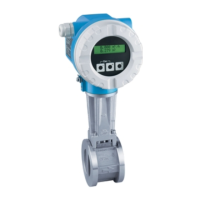
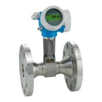
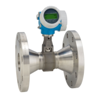
Proline Prowirl 73 F, W
Endress+Hauser 11
Inlet and outlet run As a minimum, the inlet and outlet runs shown below must be observed to achieve the specified accuracy
of the device. The longest inlet run shown must be observed if two or more flow disturbances are present.
A0001867
Minimum inlet and outlet runs with various flow obstructions
A = Inlet run, B = Outlet run
1 = Reduction
2 = Extension
3 = 90° elbow or T-piece
4 = 2 x 90° elbow, 3-dimensional
5 = 2 x 90° elbow
6 = Control valve
Note!
A specially designed perforated plate flow conditioner can be installed if it is not possible to observe the inlet
runs required (→ Page 12).
Outlet runs with pressure measuring point
If a pressure measuring point is installed after the device, please ensure there is sufficient enough distance
between the device and the measuring point to avoid effects caused by the generated vortices.
A0001866
Installing a pressure measuring point (PT)
Esc
E
-
+
Esc
E
-
+
Esc
E
-
+
Esc
E
-
+
15 x DN 5 x DN
A
1
3
5
2
4
6
A
A
A
A
A
B
B
B
B
B
B
18 x DN 5 x DN
20 x DN
5xDN
40 x DN 5 x DN
25 x DN
5xDN
50 x DN
5xDN
Esc
E
-
+
Esc
E
-
+
PT
3...5 x DN
Esc
E
-
+

 Loading...


