Commissioning Proservo NMS80
62 Endress+Hauser
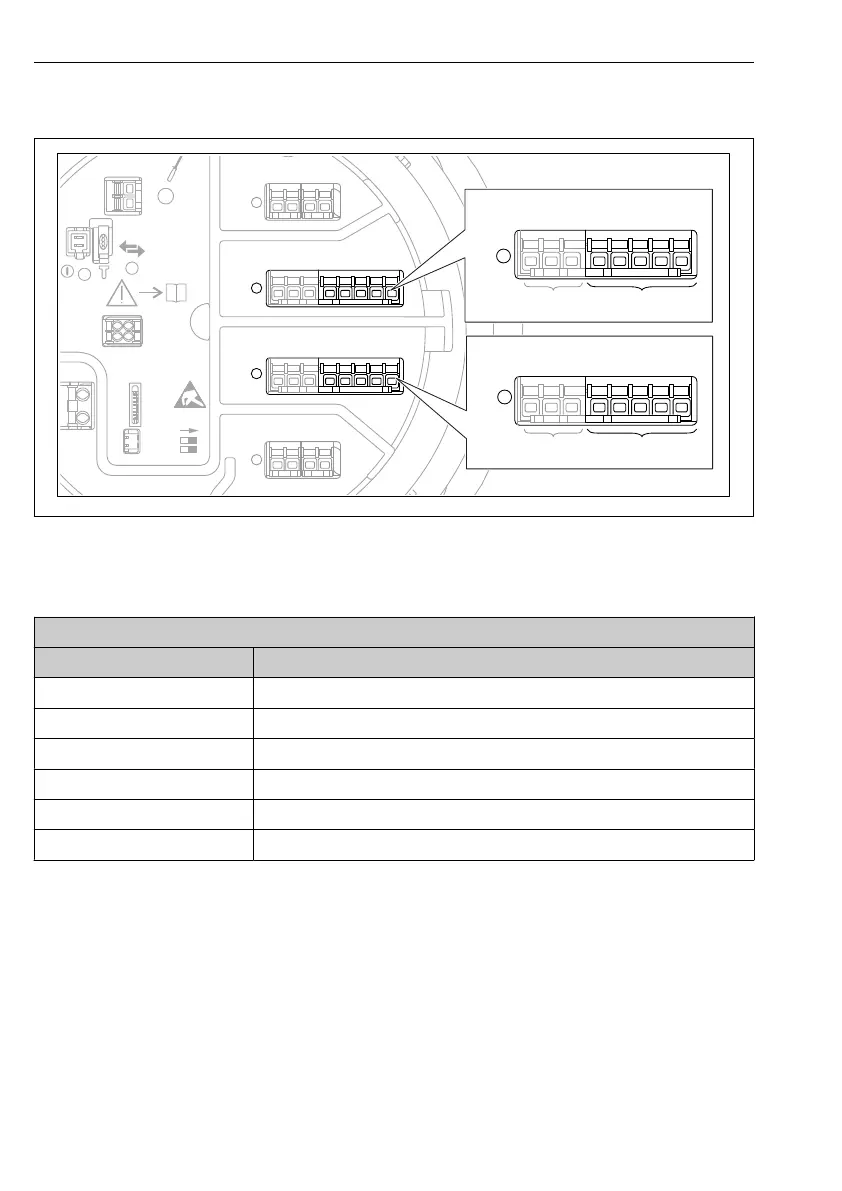
7.5.3 Configuration of a connected RTD
D
E
F
C
B
A
1
1
1
1 3
2
2 4
1
HR
CDI
WP
on
SIM
2
2
3
3
4
4
1 2 3
4 5 6 7 8
POWER
i
1 2 3 4 5 6 7 8
B
B1-3 B4-8
1 2 3 4 5 6 7 8
C
1 2 3 4 5 6 7 8
C1-3 C4-8
A0032465
32 Possible locations of the Analog I/O modules, to which an RTD can be connected. The order code
of the device determines which of these modules is actually present.
Submenu: Setup → Advanced setup → Input/output → Analog IP
Parameter Meaning / Action
RTD type Specify the type of the connected RTD.
RTD connection type Specify the type of connection of the RTD (2-, 3- or 4-wire).
Input value Check whether the indicated value matches the actual temperature.
Minimum probe temperature Specify the minimum approved temperature of the connected RTD.
Maximum probe temperature Specify the maximum approved temperature of the connected RTD.
Probe position Enter the mounting position of the RTD (measured from the datum plate).

 Loading...


