Commissioning Proservo NMS80
64 Endress+Hauser
7.5.4 Configuration of the digital inputs
D
E
F
C
B
A
1
1
1
1 3
2
2 4
1
HR
CDI
WP
on
SIM
2
2
3
3
4
4
1
1
2
2
3
3
4
4
5
5
6
6
7
7
8
8
POWER
i
C
1
2 3 4 5 6 7
C1-2 C3-4
A1-2 A3-4
A
1 2 3 4
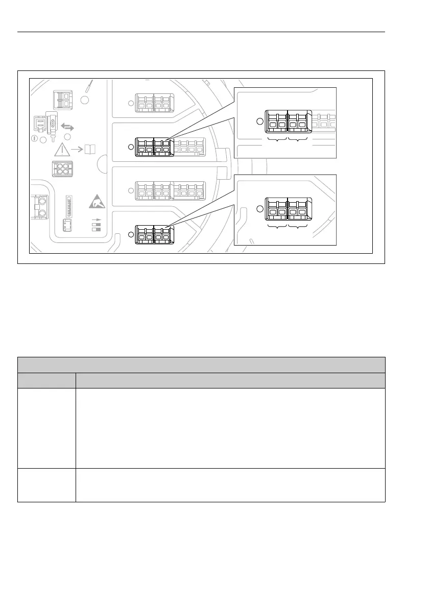
A0026424
33 Possible locations of the Digital I/O modules (examples); the order code defines the number and
location of digial input modules.
There is a Digital Xx-x for each digital I/O module of the device. "X" designates the slot in the
terminal compartment, "x-x" the terminals within this slot. The most important parameters of
this submenu are Operating mode and Contact type.
Submenu: Setup → Advanced setup → Input/output → Digital Xx-x
Parameter Meaning / Action
Operating mode Select the operating mode (see diagram below).
• Input passive
The DIO module measures the voltage provided by an external source. Depending on the status
of the external switch, this voltage is 0 (switch open) or exceeds a certain limit voltage (switch
closed). These two states represent the digital signal.
• Input active
The DIO module provides a voltage and uses it to detect whether the external switch is open or
closed.
Contact type Determines how the state of the external switch is mapped to the internal states of the DIO module
(see table below). The internal state of the Digital Input can then be transferred to a Digital Output
or can be used to control the measurement.