Operation RIA45
16 Endress+Hauser
A0010223
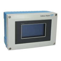
3 Display of the process indicator
1 Channel indicator: 1: analog input 1; 2: analog input 2; 1M: calculated value 1; 2M: calculated value 2
2 Dot matrix display for TAG, bar graph, unit
3 Limit value indicators in the bar graph
4 "Operation locked" indicator
5 Green LED; on - supply voltage applied
6 Red LED; on - error/alarm
7 Yellow LED; on - relay 1 energized
8 Yellow LED; on - relay 2 energized
9 Minimum/maximum value indicator
In the event of an error, the device switches automatically between displaying the error and
displaying the channel, see the "Device self-diagnosis, ..." and "Troubleshooting" sections of the
Operating Instructions.
6.3 Symbols
6.3.1 Display symbols
The device is locked / operator lock; the device setup is locked for changes to parameters; the display can
be changed.
1 Channel one (Analog in 1)
2 Channel two (Analog in 2)
1M First calculated value (Calc value 1)
2M Second calculated value (Calc value 2)
Max Maximum value/value of the maximum indicator of the channel displayed
Min Minimum value/value of the minimum indicator of the channel displayed

 Loading...

