Section 6 Weld control 36
Valves
iPAK2 controls have eight digital outputs or valves (AV1 – AV8) that can be operated independently
during a weld sequence. The valves are categorised as WAV, motor
1
or AUX valves.
A WAV valve turns on at start of sequence and turns off at the end of the Hold interval.
The operation of a motor valve is determined by the 2
nd
stage test (Section 12 Configuration).
An AUX valve may be programmed to come on during any interval of the weld sequence,
including the Off time in repeat mode.
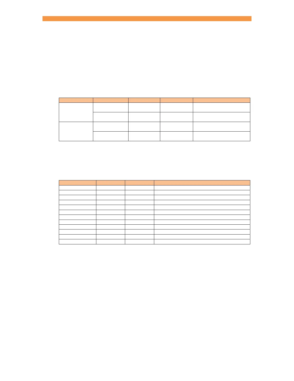
Mode Configuration WAV function Motor function Description
spot
Single electrode AV1 n/a
AV1 is automatically
selected
Multi-electrode
1
AV1 – AV8 n/a
Any combination of AV1 to
AV8 may be selected
seam
1
Single electrode AV1 AV2
AV1 and AV2 are
automatically selected
Multi-electrode
1
AV1 – AV8 AV1 – AV8
Any combination of AV1 to
AV8 may be selected
1
Extended feature
Valves not being used for the WAV or motor function may be used as AUX valves. WAV/motor settings
always override any corresponding AUX settings.
The weld programs contain the following valve control parameters.
Parameter Units Range Description
WAV AV1
AV8 WAV output
Motor
1
AV1 – AV8 Motor output
Squeeze AV1 – AV8 on/off Valve states during the Squeeze interval
Pre-heat AV1 – AV8 on/off Valve states during the Pre-heat interval
Cool1 AV1
AV8 on/off Valve states during the Cool1 interval
Upslope AV1
AV8 on/off Valve states during the Upslope interval
Main heat AV1
AV8 on/off Valve states during the Main heat interval
Cool2 AV1 – AV8 on/off Valve states during the Cool2 interval
Downslope AV1 – AV8 on/off Valve states during the Downslope interval
Post-heat AV1
AV8 on/off Valve states during the Post-heat interval
Hold AV1
AV8 on/off Valve states during the Hold interval
Off
2
AV1
AV8 on/off Valve states during the Off interval
1
Seam mode only.
2
Repeat mode program option must be enabled to use this feature.