Section 12 Confi
uration 63
2
Analog control
In this mode of operation, the inverter output current can be controlled by applying a 0 to 10 Volt signal to P4 pins
1(+) and 2(-). A Seam sequence is produced, but note:
Pre-heat and post-heat are not available
Force feedback is not available
The input signal will control a different parameter depending on the mode set in the selected weld program:
Main mode 0 to 10 V input signal controls
P/W 0 to 100% pulse-width
CCu 0 to 100% heat
CCC 0 to 100% current
3
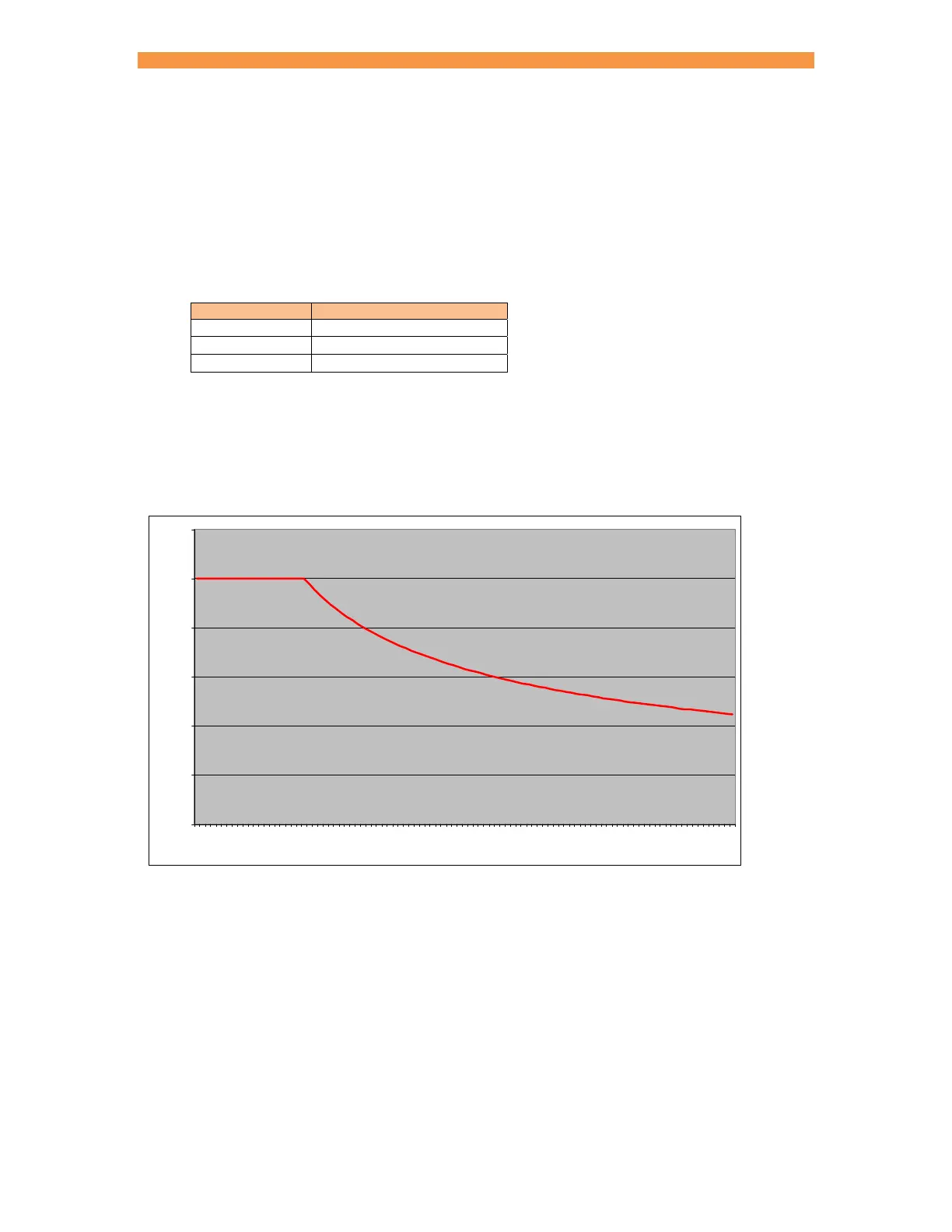
Duty cycle limiter
Duty is calculated over a 2 second averaging time. The inverter rating applies at up to 20% duty. At higher duties
the maximum output current must be de-rated as shown by the curve below:
The iPAK2 protects against weld sequences that would exceed the allowable duty cycle. In this event the inverter
will
Stop at the end of a spot weld
Stop immediately in a seam weld
The READY signal will be de-asserted and an error message given. Further initiation is prohibited. Perform a
‘RESET FAULT’ operation to clear.
0.00
0.20
0.40
0.60
0.80
1.00
1.20
0 102030405060708090100
% Du t y
De-rating factor