EMW90HDNC1U Air-cooled Chiller
2.2 Implement
2.2.1 System Principle
The EMW series chiller is composed of a
refrigeration cycle system and a coolant cycle
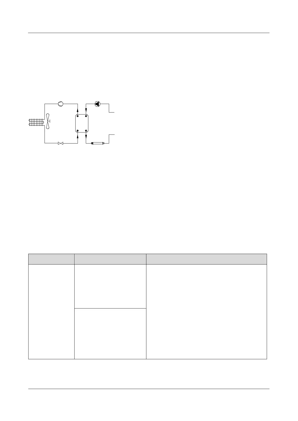
system, and the system principle is shown in
Figure 2-2.
Figure 2-2 System principle
1
2
3
4
5
7
6
From the load side
To the load side
1: Compressor 2: Condenser
3: Condenser fan 4: Throttle element
5: Plate heat
exchanger
6: Circulation pump
7: Electrical heater
The working process of EMW series air-cooled
chillers is as follows:
1. When the outlet coolant temperature reaches
the refrigeration opening point, the
compressor starts to compress the gaseous
refrigerant.
The chiller supports the execution of
temperature control logic based on the outlet
coolant temperature and the cell temperature
sent by the host computer.
2. The condenser condenses the
high-temperature refrigerant, and the
refrigerant changes from a gaseous state to
a liquid state.
3. The fan sucks in the outside air and
discharges the heat released when the
refrigerant condenses to the surrounding air.
4. The throttling element (electronic expansion
valve) throttles and depressurizes the
condensed refrigerant.
5. The refrigerant enters the plate heat
exchanger to evaporate and absorb the heat
of the coolant flowing through the plate heat
exchanger.
6. The circulating pump continuously transports
the coolant to the plate heat exchanger,
exchanges heat with the refrigerant, and
transports the cooled coolant to the container
to cool the battery pack.
2.2.2 Control Logic
The control logic of EMW90HDNC1U chiller is shown in Table 2-3.
Table 2-3 Control logic
Item Control Logic Description
Refrigeration
Refrigeration demand ≥
50%: the refrigeration is
started.
Refrigeration demand (%)= (actual control
temperature - refrigeration set point) /
refrigeration sensitivity * 100%
When the refrigeration set point is 15°C and the
refrigeration sensitivity is 3°C, the refrigeration
start point is 16.5°C (15°C +3°C* 100% =16.5°C),
and the refrigeration stop point is 13.5°C (15°C
-3°C*50%=13.5°C).
When the outlet coolant temperature is used as
the actual control temperature:
When the outlet coolant temperature is ≥
16.5°C, the chiller will start cooling.
When the outlet coolant temperature is ≤
, the chiller stops cooling.
Refrigeration demand ≤
-50%: the refrigeration is
stopped.