EMW90HDNC1U Air-cooled Chiller
damage is found, please report it to the seller
with the barcode number on the outside of the
package within one week.
Please count the number of units and
installation accessories according to the list of
accessories.
Before disposing of the packaging materials,
please make sure that there are no loose parts
in the packaging materials. In order to protect
the environment, it is recommended to recycle
the packaging boxes.
3.2.2 Tools Preparation
Before installation and maintenance, please
prepare not limited to the commonly used tools
listed in Table 3-2. On-site technicians can
increase or decrease them according to the
actual situation.
Table 3-2 Commonly used tools
Tool Icon Function
Flat-blade
screwdriv
er
(2mm×75
mm)
A flat-blade screwdriver
installs or removes the
connecting wires of the
controller, etc.
Phillips
screwdriv
er
(M3/M4/M
5/M6)
Phillips screwdriver is
used to install or
remove screws for other
parts. Recommended
tightening torques are
as follows:
M3: 0.5N.m, M4:
1.2N.m, M5: 2.7N.m,
M6: 4.2N.m
Torque
wrench
(Setting
value:
5~25N.m,
scale:
0.25N.m)
Used for disassembly
and assembly of screws
and pipeline
connection, etc.
Tightening torque of
screws: 13N.m (M8)
Tightening torque of
chuck connection:
10N.m
Diagonal
pliers
remove the cable ties
on site.
Crimping
pliers
On-site processing of
cables and crimping of
various terminals.
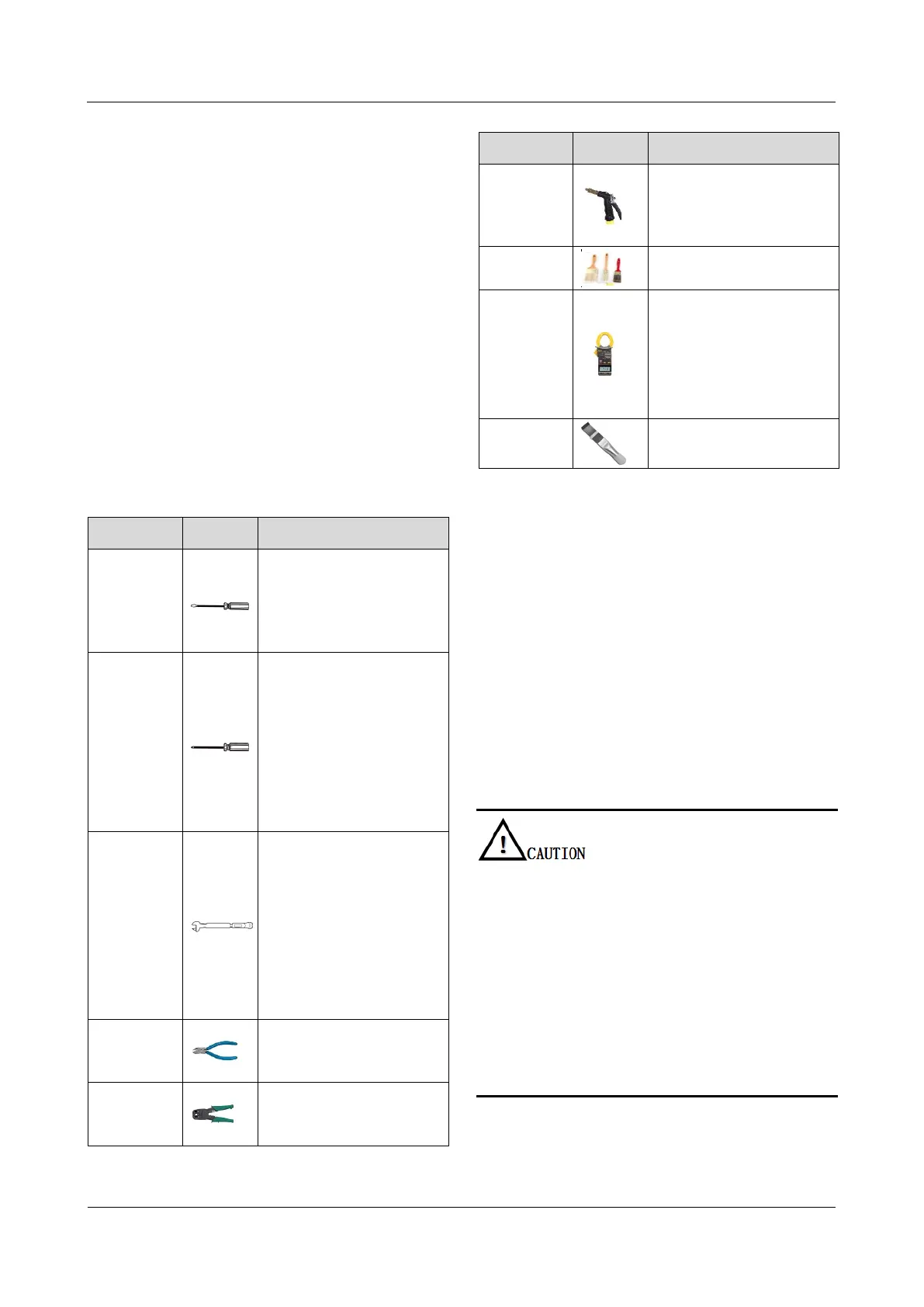
Tool Icon Function
r special
cleaning
water gun
Clean the condenser of
the air conditioning
system.
Brush
Clean up dust.
Clamp
ammeter
Check the working
voltage and current on
site.
Check the internal
power distribution
voltage and current.
Fin comb
Corrects bent and
deformed fins.
3.3 Mechanical Installation
Prerequisites
The installation location of the chiller has been
reasonably planned by referring to 3.1.2
Physical Dimension, 3.1.3 Installation
Environment and 3.1.4 Installation Layout.
The packaging of the chiller has been
disassembled, and the installation tools and
accessories listed in the packing list are ready.
The coolant pipelines (diameter: DN28, pipeline
pressure ≥ 3.5bar) have been prepared.
Precautions
The pull ring on the front of the chiller is only used for
pulling the maintenance panel. It is forbidden to use it
as a force support to move the chiller upwards.
To avoid condensation, use insulated and thermal
insulated pipes for connection.
The coolant inlet and outlet of the chiller adopts quick
connectors, and the specifications of the connecting
pipes must conform to the specifications of the coolant
inlet and outlet ports.
It is suggested to install stop valves between the inlet
and outlet connecting pipes of the chiller and the
equipment to be cooled, so as to maintain the chiller or
the equipment to be cooled later.