EMW90HDNC1U Air-cooled Chiller
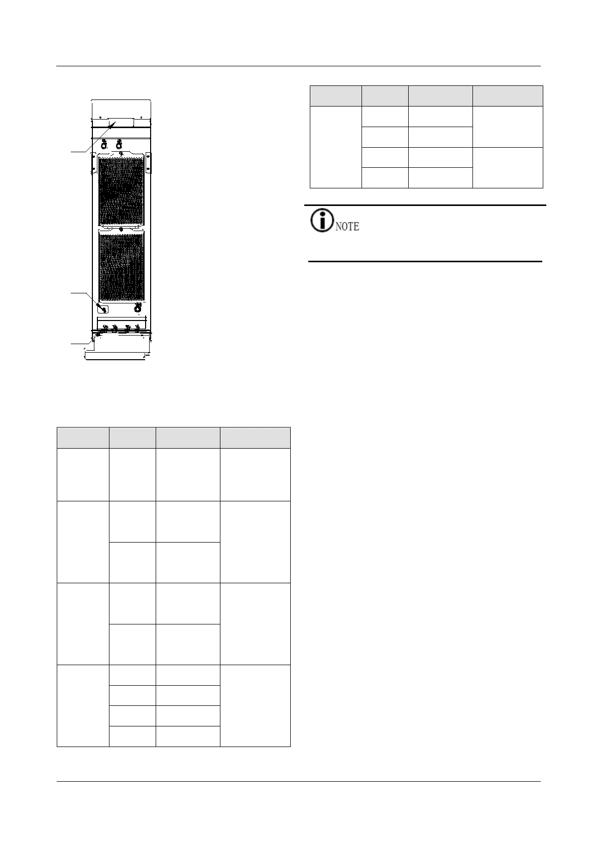
Figure 3-2 User wiring interface
1: Circuit breaker 2: Ground nut
Table 3-3 Definition of electrical interface pins
Type Pin Definition Description
Ground
See
Figure
3-2
mark
PE -
POWER
A
supply L
the chiller.
B
Single-pha
supply N
PUMP
C
Single-pha
supply L
Power
filling pump.
D
supply N
DEBUG
E 12V+
Field
communicat
or
communicati
on interface.
F GND
G D3+
H D3-
Type Pin Definition Description
COM
A CAN+
communicati
on interface.
B CAN-
C RS485+
RS485
communicati
on interface.
D RS485-
The pins not listed in the DEBUG interface and COM
interface are reserved.
Procedure
Step 1 Confirm that the chiller has been
disconnected.
Step 2 Refer to Table 3-3 to connect and tighten
the power cord and communication cord.
Step 3 Turn on the circuit breaker of the chiller.
Remove the cover on the circuit breaker
(see mark 1 in Figure 3-2), turn on the
circuit breaker and install the cover back.