User Manual
Gobi-640-17µm and Gobi-384-25µm-GigE, CL, CXP Camera
4. Electrical Interface
4.1. General Overview Connectors and Specifications
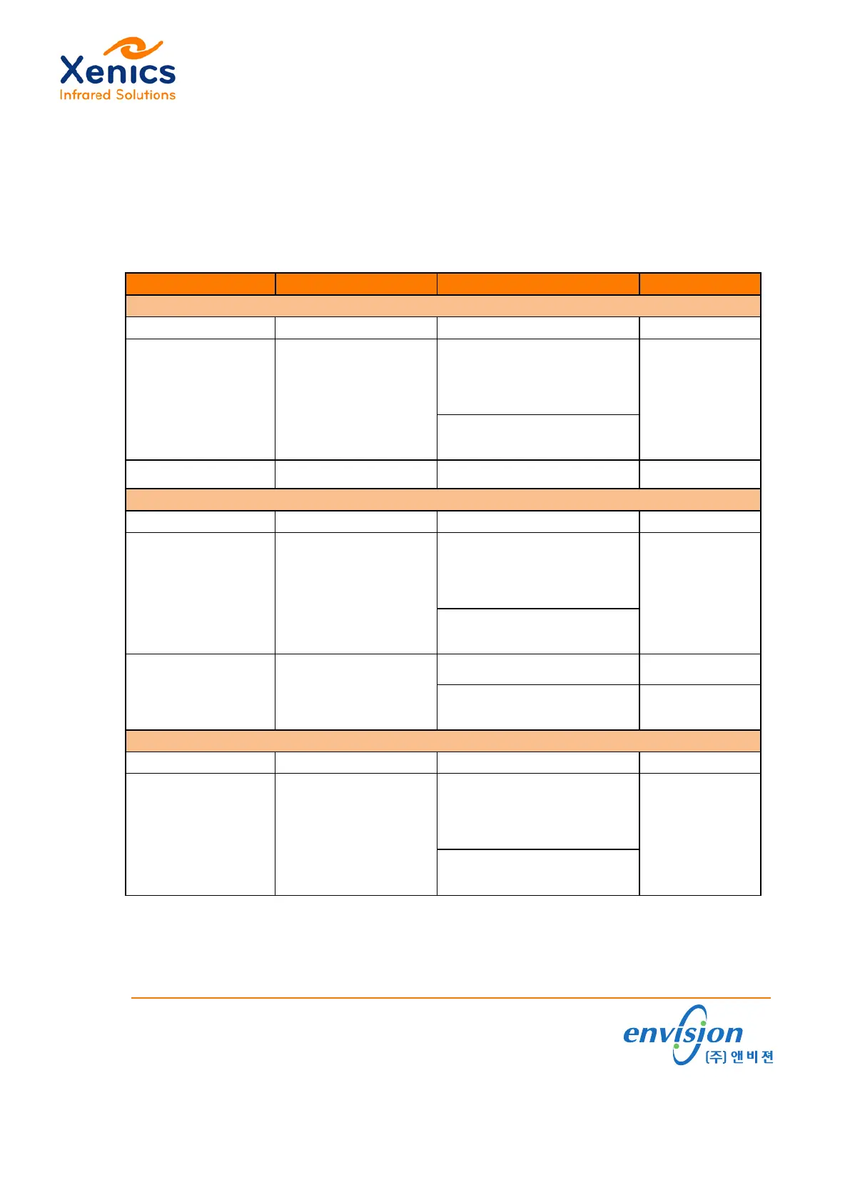
Connect all cables to the connectors at the camera back (see also (Ref. 2)). Table 4-1 lists
the connector and interface specifications overview of the Gobi-640-17µm and of the Gobi-
384-25µm.
Interface Connector Specification Camera Protocol
Gobi-640-GigE and Gobi-384-GigE
Input power (12V DC) Hirose HR10-7R-4SA(73) 12V ±10%
Trigger (either Trigger-
in or Trigger-out!)
SMA
V
IN,L
= 0.8V Max.
V
IN,H
= 2V Min.
V
IN,MAX
= 30V
Internal Pull-down: R = 10kΩ
Trigger out:
V
HIGH
= 3.3V ±10%
Ethernet RJ45 connector GigE standard GigE Vision
Gobi-640-CL and Gobi-384-CL
Input power (12V DC) Hirose HR10-7R-4SA(73) 12V ±10%
Trigger (either Trigger-
in or Trigger-out!)
SMA
V
IN,L
= 0.8V Max.
V
IN,H
= 2V Min.
V
IN,MAX
= 30V
Internal Pull-down: R = 10k
Ω
V
HIGH
= 3.3V ±10%
Mini-camera link
CONN SDR 26POS
VERT RECEPT
Serial control: 115200 baud, 8n1
Levels: RS-644
XSP Protocol
(see (Ref. 1))
Image acquisition: CL
CL Base protocol/
1 TAP for image
Gobi-640-CXP
CoaXPress BNC connector CXP-1 (or CXP-2) CXP
Trigger (either Trigger-
in or Trigger-out!)
SMA
Trigger in:
V
IN,L
= 0.8V Max.
V
IN,H
= 2V Min.
V
IN,MAX
= 30V
Internal Pull-down: R = 10k
Ω
V
HIGH
= 3.3V ±10%
Table 4-1 Electrical interface specs for Gobi-640/Gobi-384-GigE, CL, CXP interface
www.envision.co.kr •Supporting your Vision
(주)앤비젼 서울시 금천구 가산동 550-1 IT캐슬 1동 603호 (153-768)
Tel. 02. 2624. 5503 Fax. 02. 2082. 6427 e-mail. sales@envision.co.kr
 Loading...