User Manual
Gobi-640-17µm and Gobi-384-25µm-GigE, CL, CXP Camera
4.6. Gobi-640/Gobi-384-CL Interface
Camera Link is an interface for the transfer of digital video data. The standard defines data
transfer on a physical base and determines connectors, cables and components for
transmission and reception. Different configurations are available, distinguishing between
the numbers of parallel transferred data bits.
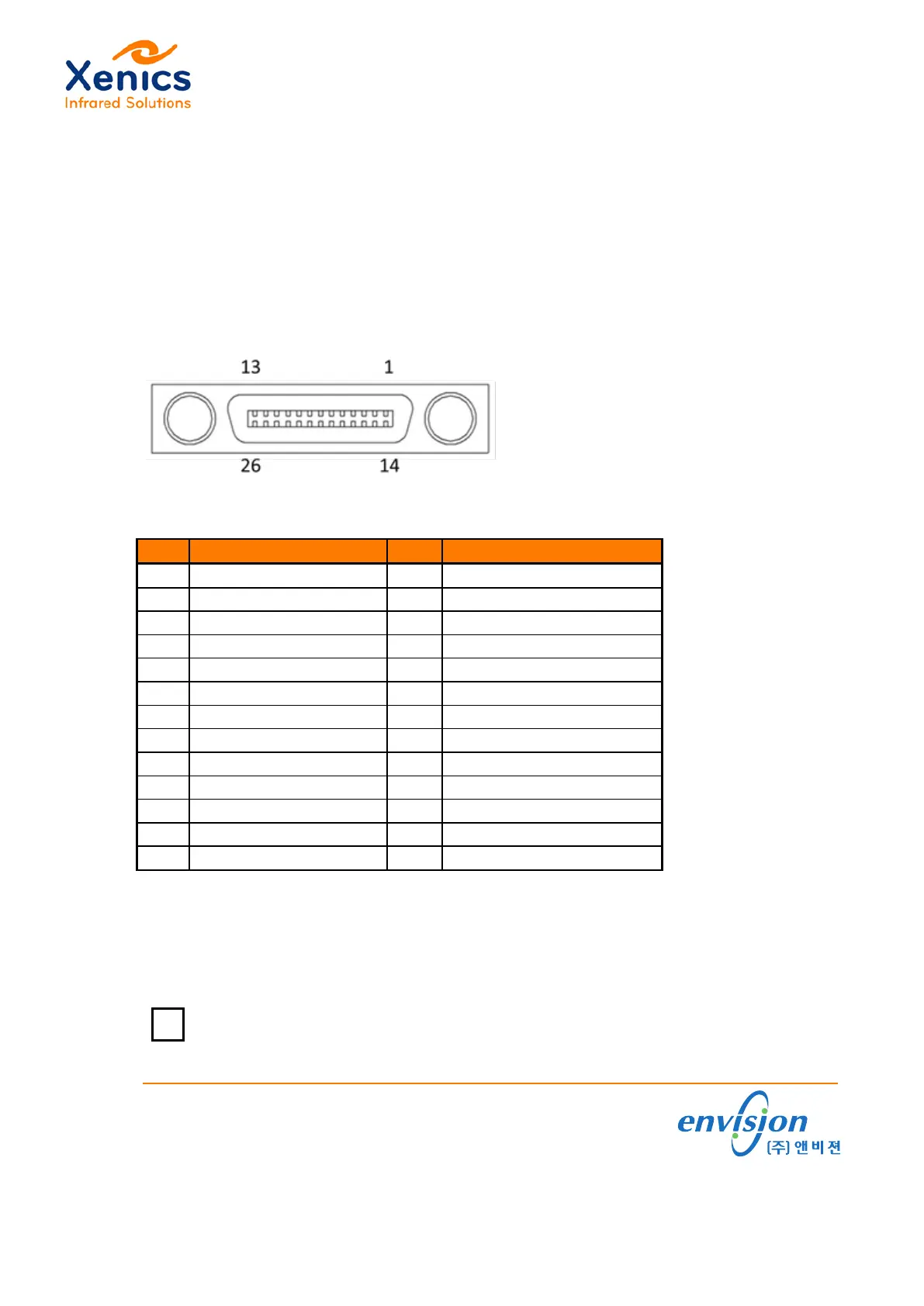
For the Gobi-CL camera, the BASE configuration with 1 TAP is used. The pin
assignment and pin lay-out of the Camera Link connector on the Gobi-CL camera are
shown in Figure 4-3 and Table 4-4.
Figure 4-3 Pin out of Camera Link connector on the Gobi-640-CL camera
Signal
Signal
1 GND 14 GND
2 X0 15 X0+
3 X1 16 X1+
4 X2 17 X2+
5 XCLK 18 XCLK+
6 X3 19 X3+
7 SerTC+ 20 SerTC-
8 SerTFG- 21 SerTFG+ P
9 CC1 22 CC1+
10 CC2+ 23 CC2
11 CC3 24 CC3+
12 CC4+ 25 CC4
13 GND 26 GND
Table 4-4 Camera Link connector (base) pin assignment
CC1 can be configured as trigger input.
CC2 to CC4 in Table 4-4 are not supported by the camera. The clock rate is 16 MHz with
one tap & 16 bit/pixel.
Information about the timing diagram can be found in (Ref. 4)
www.envision.co.kr •Supporting your Vision
(주)앤비젼 서울시 금천구 가산동 550-1 IT캐슬 1동 603호 (153-768)
Tel. 02. 2624. 5503 Fax. 02. 2082. 6427 e-mail. sales@envision.co.kr
 Loading...