User Manual
Gobi-640-17µm and Gobi-384-25µm-GigE, CL, CXP Camera
4.2. Power Interface
The power cable (ASY-001268) must be connected to the backside of the camera (see
(Ref. 2) for its location). For a Gobi-GigE, the power cable does not need to be connected
to the camera in case Power over Ethernet (PoE) is foreseen.
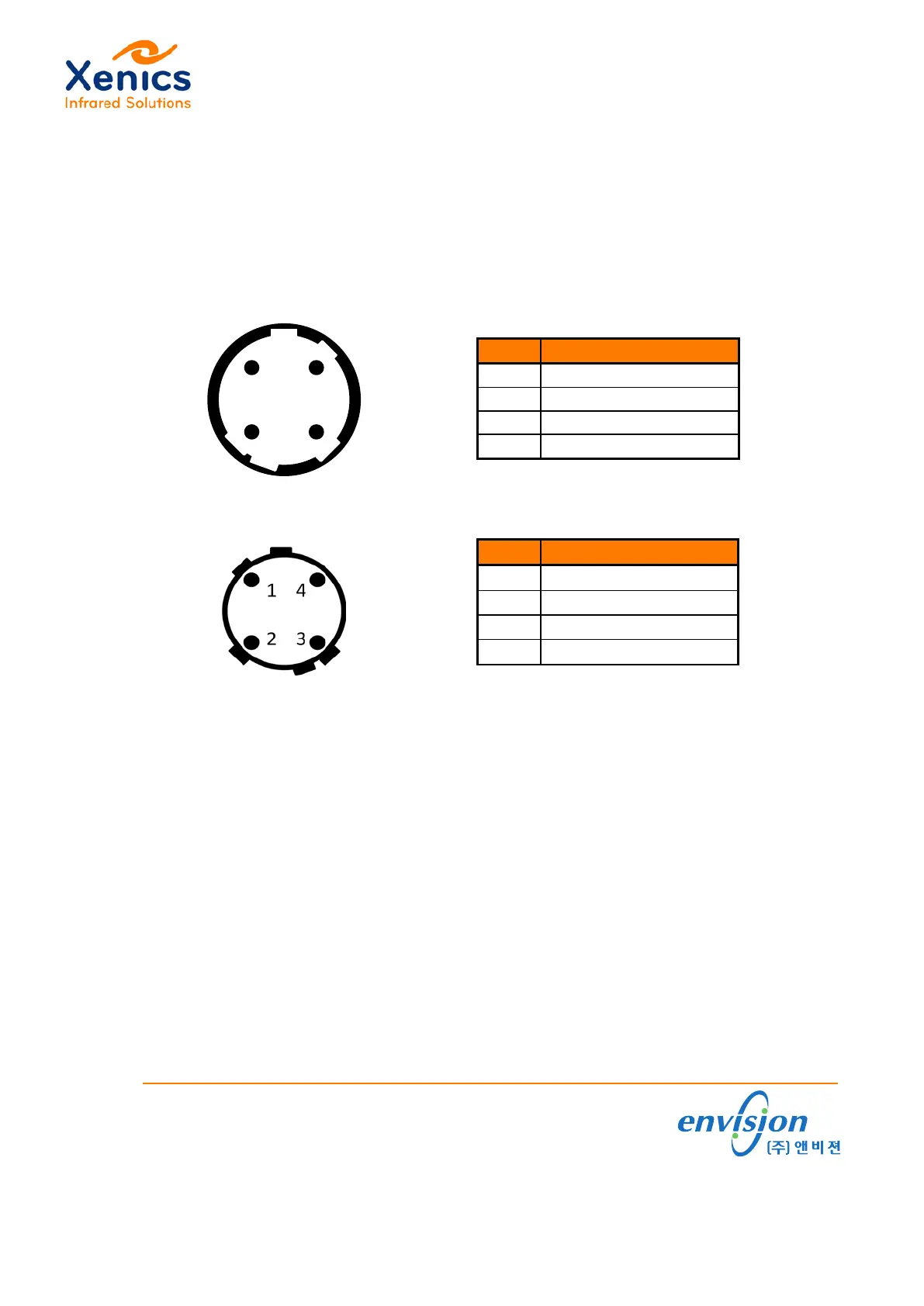
Figure 4-1
shows schematically the pin location of the power connector on the camera
(Hirose HR10-7R-4SA(73)). Table 4-2 lists the connector pins overview.
Pin Signal
1 + 12V
2 + 12V
3 Gnd
4 Gnd
Figure 4-1 Camera power connector
Table 4-2 Camera power connector 12V
DC
Pin Signal
1 + 12V
2 + 12V
3 Gnd
4 Gnd
Figure 4-2 Cable connector
Table 4-3 Cable connector 12V
DC
For the power cable (ASY-001268) the connector pins overview is shown in Table 4-3.
Figure 4-2 shows schematically the pin location of the cable connector (Hirose HR10-7P-
4P(73)).
www.envision.co.kr •Supporting your Vision
(주)앤비젼 서울시 금천구 가산동 550-1 IT캐슬 1동 603호 (153-768)
Tel. 02. 2624. 5503 Fax. 02. 2082. 6427 e-mail. sales@envision.co.kr
 Loading...