7
Installation steps:
Step1:Determination of Installation Location and Heat-dissipation Space
Determination of installation location: The inverter/charger shall be installed in a place with
sufficient air flow through the dissipation pad of the inverter/charger and a minimum clearance of
150 mm from the upper and lower edges of the inverter/charger to ensure natural thermal
convection. Please see Figure 2-1: Mounting.
WARNING: Risk of explosion!
Never install the inverter/charger with flooded batteries in a sealed enclosure! Do not
install the device in a confined area where battery gas can accumulate.
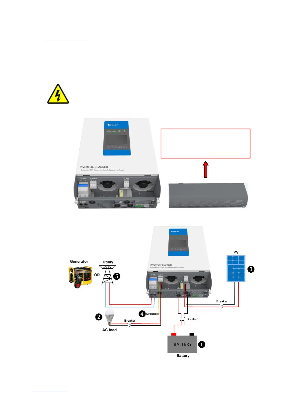
Step 2:Take down the terminal protective cover
Step 3:Wiring
※Screw off the screws and take
down the terminal protective
cover of the inverter/charger
before wiring.
 Loading...