8
Connect the system in an order of battery load PV array
GroundUtility in accordance with Figure 2-3: Wiring Diagram. Disconnect the
system in the reverse order.
Warning: Danger, High-voltage! Utility input, AC output and PV array will produce
dangerous voltage, make sure to disconnect the circuit breaker/ fuse before wiring.
Warning: Do not turn on the circuit breaker/ fuse when wiring, and at the same time,
ensure that the wiring of “+”, “-” are correctly connected.
Warning: A circuit breaker must be installed at the battery end, for selection, refer to
Section 2.3 "Wire and Circuit Breaker".
NOTE: If the inverter/charger is to be used in an area with frequent lightning strikes, it is
recommended to install an external surge arrester at the PV input.
Grounding
Grounding connection must be made when utility is connected to the inverter/charger. The
inverter/charger has dedicated grounding terminal as shown in Fig. 2-3, the grounding must be
reliable, the grounding wire have to stay consistent with Recommended wire for AC output, the
grounding point shall be as close as possible to the inverter/charger, the grounding wire shall be as
short as possible.
AC output, Ground and PV wiring terminal use way:
①When wiring, do not close the circuit breaker, and it is necessary to use a slotted screwdriver to
unscrew the screws for connecting their corresponding wires.
②When removing the wirings, first the integrated machine must stop working, and then the screws
shall be unscrewed by using a slotted screwdriver, so as to dismantle their corresponding wires.
Step 4: Install the terminal protective cover
Step 5:Connect accessory
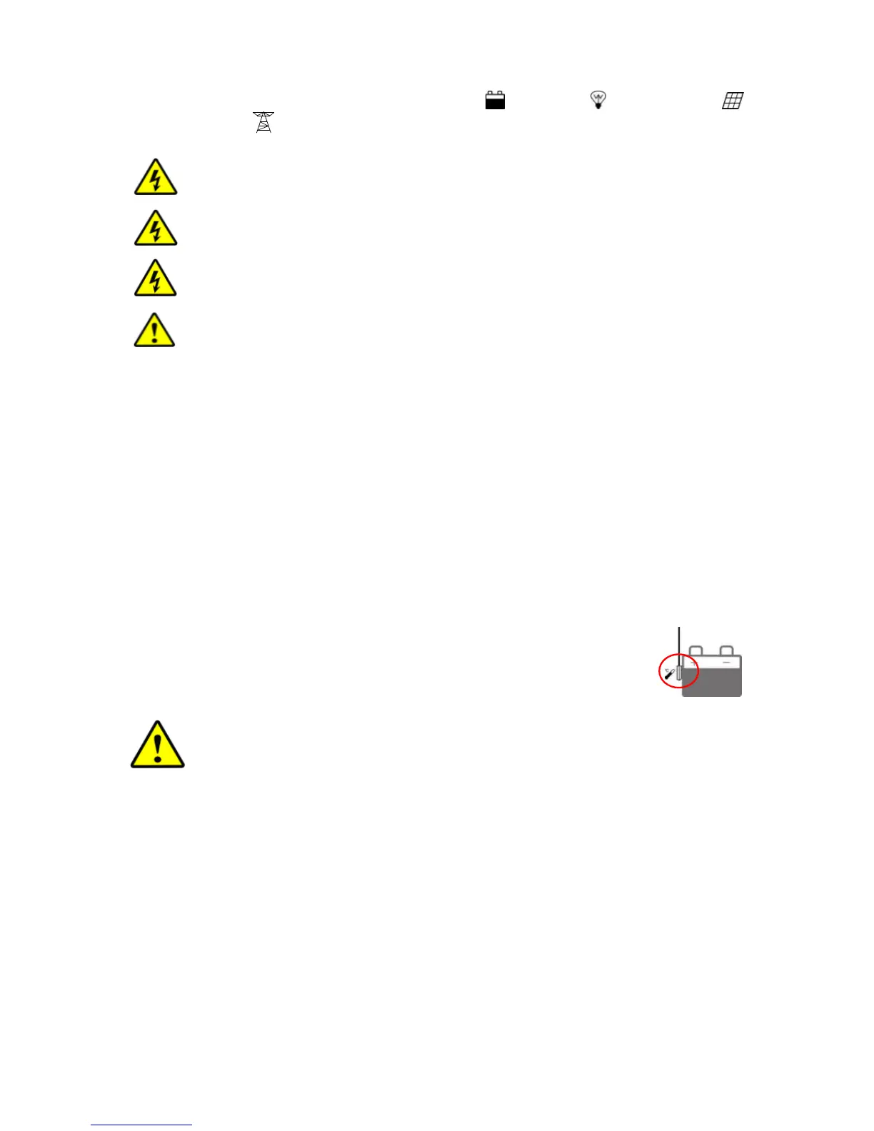
Connect the remote temperature sensor cable (model: RTS300R47K3.81A)
Connect one end of the remote temperature sensor cable to the interface⑥
and place the other end close to the battery.
NOTE: Connect the temperature sensor, the inverter/charger is compensated
according to the ambient temperature.
Step 6:Recheck if the wire connection is correct
Step 7:Power on the inverter/charger
①Turn on the circuit breaker at the battery end.
②Switch on the switch then the inverter indicator is on.
③Turn on the breaker of PV array and Utility.
④Turn on the AC load when the AC output is normal.
 Loading...