GENERAL
The
DIP Switch No. 2 consists of
the
following
4 pins. A summary
of
the
functions
and
their
respective DIPswitch pins
and
factory settings
at
the
time
of
shipment
are
shown
in
table
6-6.
TABLE
6-6.
Functions
of
DIP
Switch
No.
2
(FX-80/80+
/100/100+
)
SW
pin
No.
Function
OFF
ON
Factory-set
condition
2-1
SLCT IN signal internally
fixed
or
not
fixed
Not
fixed
Fixed
ON
2-2
Bu22er
Invalid
Valid
ON
2-3
1
inch
skip-over
perforation
Invalid
Valid
OFF
2^
Autonnatic
line
feed
LF
must
be
from
host
Auto
LF
with
CR
OFF
SW2-1:
When
the
switch
is
ON,
the printer
is
permanently
inthe
"select"
mode
and
no
external
command
can
"deselect
it. In
the
OFF
position, it theoretically can be selected
and
deselected by
external
software
codes.
This
refers
to
pin
36
on
the
connector.
Some
computers
control this pin; if
they
do
control
the
pin, SW
should
be
OFF.
SW2-2: IfON,
the
buzzer will
sound;
if
OFF,
the
buzzer
will
not
sound
at
all.
SW2-3
This pin is used to set
the
automatic skip-over perforation
function.
:
i
6-6
EPSON
PRINTERS
SW2-4: Forces an
automatic
line-feed
with
each
carriage
return.
When
OFF,
line-feed must be provided via
software
as
needed.
This pin
is used
to
fix AUTO
FEED
XTsignals internally,
the
signal line is
wired ORed with pin No. 14 of
the
interface connector. In order
to
control pin No. 14, leave this DIPswitch in
the
OFFposition.
6.3.3
RX-80/80FT
+
/RX-100/100
DIP
Switches
To
obtain
access
to
the
DIP Switches,
follow
the
steps
below;
1.
Unplug
the
power
cord.
2. Remove
the
pin-feed
paper
(if loaded)
and
the
separator.
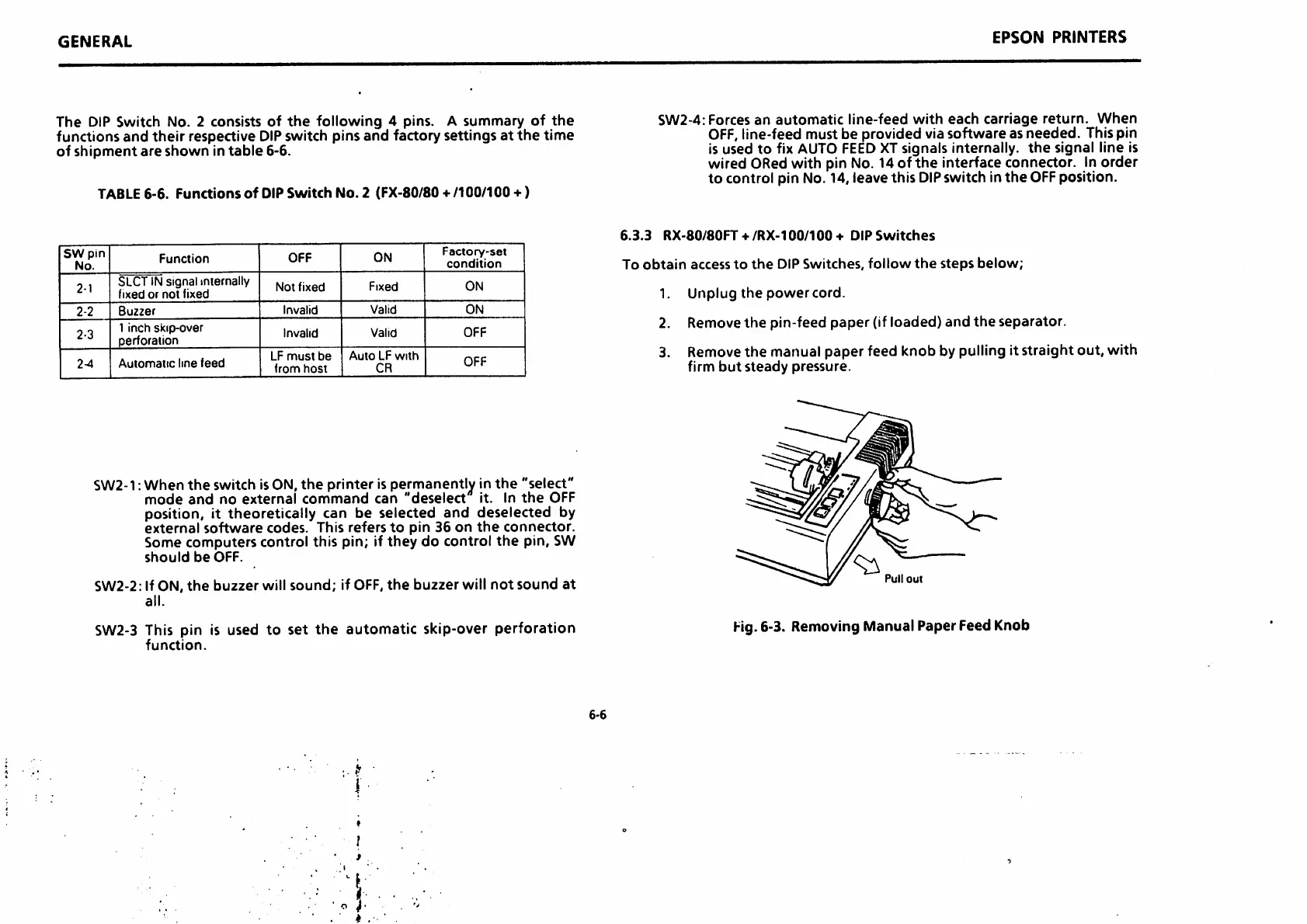
3. Remove
the
manual paper feed knob by pulling it straight out, with
firm
but
steady
pressure.
Pull
out
Fig.6-3. Removing Manual Paper Feed Knob

 Loading...


