EPSON
PRINTERS
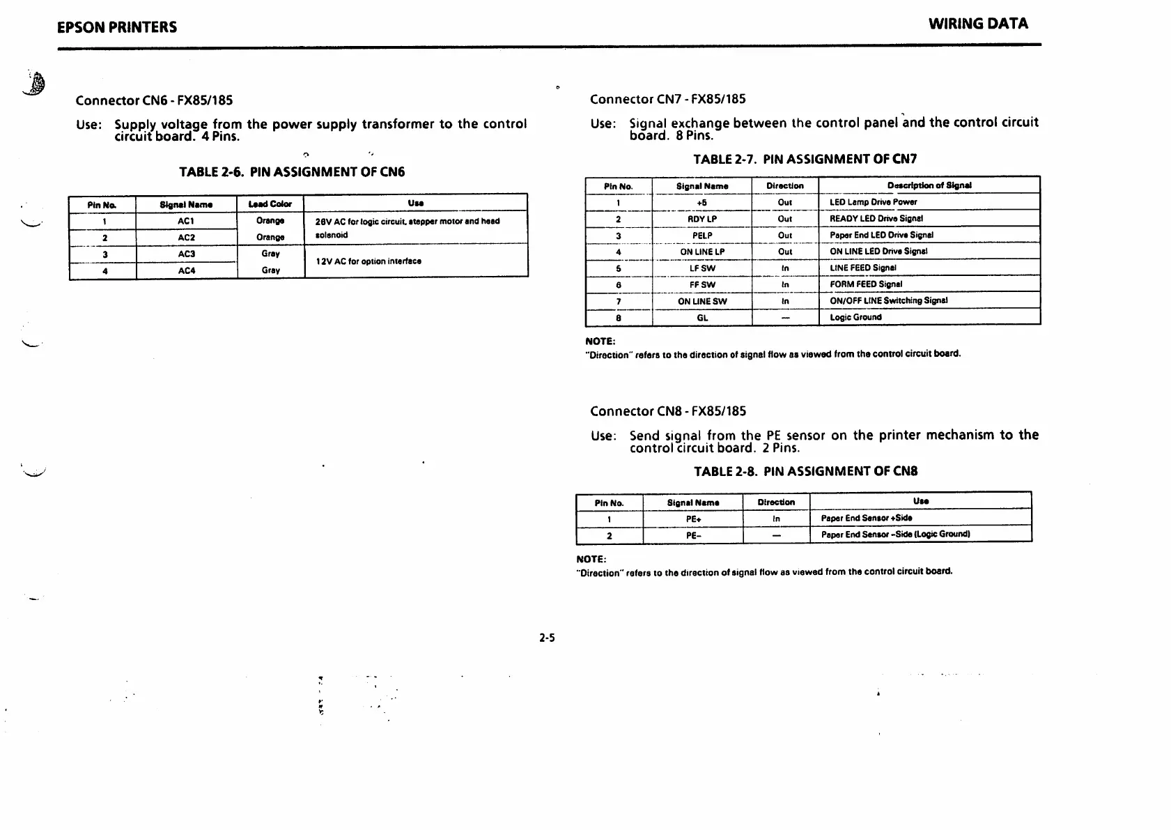
Connector
CN6-FX85/185
Use:
Supply
voltage
from
the
power
supply
transformer
to
the
control
circuit
board.
4
Pins.
WIRING
DATA
Connector
CN7-FX85/185
Use: Signal exchange between the control panel and
the
control circuit
board.
8
Pins.
TABLE
2-7.
PIN
ASSIGNMENT
OF
CN7
TABLE
2-6.
PIN
ASSIGNMENT
OF
CN6
Ptn
No.
Signal
Name
Direction
•
ascription
of
Stgnel
PinNa
Signel
Name
Color
Use
1
>6
Out
LEO
Lamp
Drive
Power
1
AC1
Orsnge
26V AC for lofltc circuit,
stepper
motor
and
head
2
RDY
LP
Out
READY LED Drive Signal
2
AC2
Orange
lolsnoid
3
PELP
Out
Paper
End LEDDrive Signal
3
AC3
Gray
12V
AC for
option
inierfaca
4
ON
LINE
LP
Out
ON LINELEDDrive Signal
4
AC4
Gray
S
LF
SW
In
LINEFEED Signal
6
FF
SW
In
FORM FEEDSignal
7
ON
LINE
SW
In
ON/OFF LINE
Switching
Signal
8
GL
-
Logic
Ground
2-5
NOTE:
"Direction" refers to the direction of signal flow as viewed from the control circuit board.
Connector
CN8-FX85/185
Use: Send signal from
the
PE
sensor on
the
printer mechanism
to
the
control
circuit
board.
2
Pins.
TABLE
2-8.
PIN
ASSIGNMENT
OF
CN8
Pin
No.
Signal
Name
Oirection
Use
1
PE+
In
Paper
End
Sentor
••'Side
2
PE-
-
Paper End Sensor -Side (LogicGround)
NOTE:
"Direction" refers to the direction of signal flow as viewed from the control circuit board.

 Loading...


