WIRING
DATA
2.3
FX-80/100
Connector
CN1
-
FX-80/100
Use: This
connector
is
used
for
data
exchange
between
the
FX-80/100
and
the
host
computer.
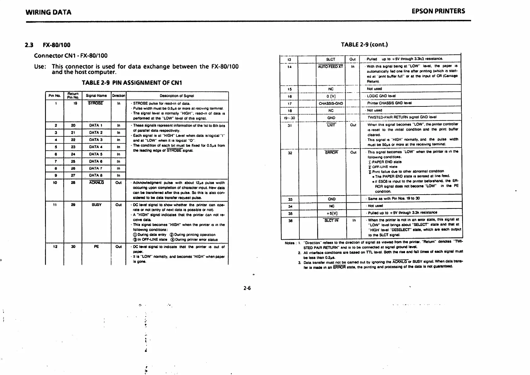
TABLE
2-9
PIN
ASSIGNMENT
OF
CN1
Pin
No.
Return
Pin
No.
Signal
Name
Oirectan
Description of Signal
t
19
"STfissr
In •
STROBE
pulse
tor
read-in
of
data.
'
Pulse
width
must
be
O.ShS or
more
at
reciuing
terminal.
• The signal level is normally
"HIGH
'; read-in ol
data
is
perfonned at the '
LOW
level of this signal.
2
20
DATA
1
In
•
These
signals
represent
information of
the
ist
to 8th
bits
of parallel
data
respectively.
•
Each
signal is at
"HIGH"
Level
when
data
is logical "I"
and
at
"LOW
when
it Is logical
"O".
•
The
condition
of
each
bit
must
be
fixed for O.SfiS from
the
leading
edge
of STROBE signal.
3
21
DATA
2 In
4
22
DATA
3
In
s
23
DATA
4 In
6
24
DATA
5
In
7
25
DATA
6
In
e
26
DATA
7
in
0
27
DATA
8 In
10
28
ACKNLQ
Out
'
AcKnowledgment
pulse
with
about
I2«js
pulse
width
occuring
upon
completion
of
cha/acter
input. New
data
can
tM
transferred
after
this
pulse.
So (his is
also
con
sidered
to
be
data
transfer
request
pulse.
11
28
BUSY
Out
• DC level
signal
to
show
whether
the
printer
can
ope-
rate
or not (entry of
next
data
is
possible
or not).
• A "HIGH"
signal
indicates
that
the
printer
can
not re
ceive
data
• This
signal
becomes
"HIGH"
when
the
primer
is in
the
following
conditions:
0 Duringdata entry (j) Duringprintingoperation
(j) In
OFF-LINE
state 0 During printer error status
12
30
pe
Out
• DC level
signal
to
indicate
that
the
printer is out of
paper.
• tt is
"LOW
normally,
and
becomes
"HIGH"
when
paper
Is
gone.
2-6
EPSON
PRINTERS
TABLE
2-9
(cont.)
13
SLCT
Out
Pulled
up to -t-SV
through
3.3kn
resistance.
14
AUTO
FEED
XT
In
With this Signal being at
"LOW
level, the paper is
automatically fed one line after pnnttng (which is
stan-
ed at pnnt buffer full" or at the input of CR (Carriage
Return).
15
NC
Not
used
16
0 [V]
LOGIC
GND
level
17
CHASSIS-GND
Printer
CHASSIS
GND
level
18
NC
Not
used
19-30
GND
TWlS1i:D-HAIR RETURN Signal GND level
31
LNIT
Out
When this signal becomes "LOW",the printercontroller
IS
reset
to the initial condition
and
the print buffer
cleared.
This signal is
HIGH"
normally,and the pulse width
must be
SO((S
or more at the receiving terminal.
32
ERROR
Out
This signal becomes
LOW
when the printer is m the
following
conditions.
X
paper
end
state
l;
OFF-LINE
state
I; Printfailuedue to other
abnormal
condition
• The PAPER END State is
sensed
at line feed.
* It ESC8 is input to the printer beforehand, the ER
ROR
signaldoes not become "LOW in the PE
condition.
33
CND
•
Seme
as
with Pin Nos. 19 to
30
34
NC
'
Not
used
33
+ 5(V)
• Pulled up to i-SV through 3.3k
resistance
38
SLCT
IN
In
• When the printer is not in an error state, this signal at
"LOW
level brings about "SELECT'
state
and that at
HIGH- level
"DESELECT'
sute,
which
are
each
output
to
the
SLCT
signal.
STED PAIRRETURN"and ia to b«
connected
at
sifiw'
ground level.
2.
All
interiacecooditionj ore baaed on
TTL
level.Boththe rise and fall timeaof each signal muil
be less than 0.2«is.
3. Data transfer must not be earned out by ignoringthe
ACKNLG
or
BUSY
signal.Whendata trsns-
fei is made in an
ERROR
state, the
printing
and processing of the data is not guaranteed.

 Loading...


