E
E ppssoon n EETT--44555500, , LL665555//665566 RReevviissiioonn BB
DDiissaasssseemmbbllyy//RR eeaasssseemmbbllyy DDeettaaiilleed d DDiissaasssseemmbbllyy//RReeaasssseemmbblly y PPrroocceedduurre e ffoor r eeaacch h PPaarrtt//UUnniitt 5500
ConfidentialConfidential
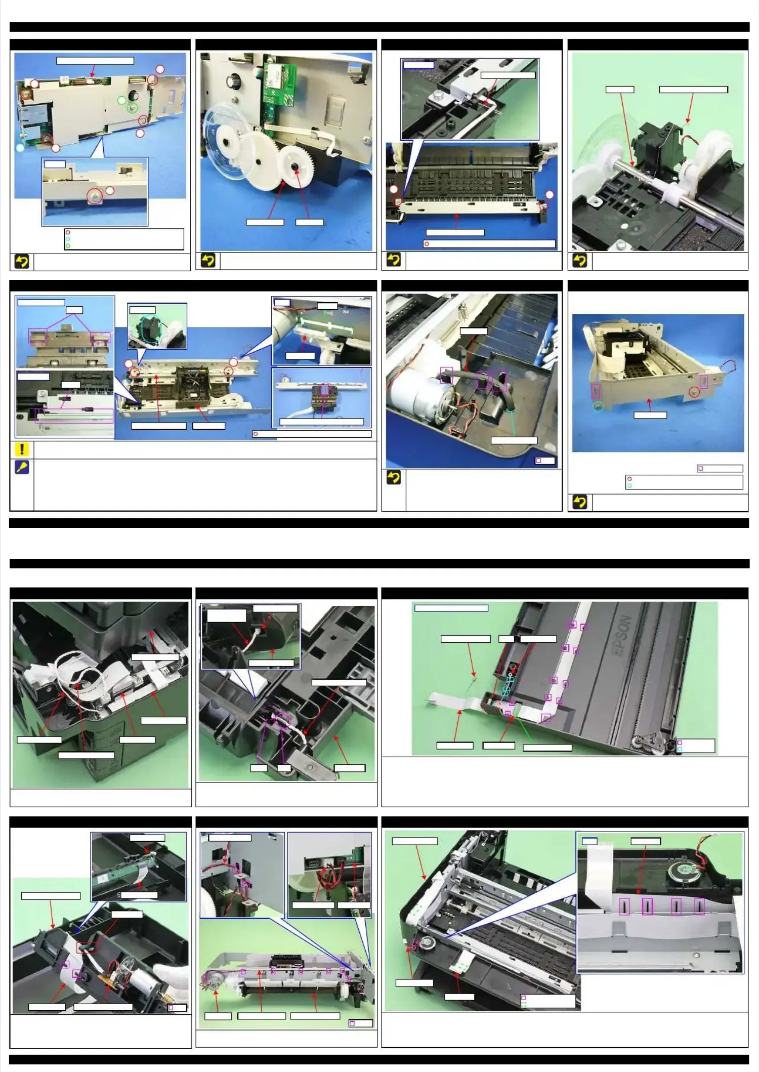
Main Board Shield Plate Upper
Main Board Shield Plate Upper
Tighten the screws in the order indicated in the figure above.Tighten the screws in the order indicated in the figure above.
Main Board Shield Plate UpperMain Board Shield Plate Upper
11
C.B.S-TITE SCREW 3x6 F/ZN-3C (4 ± 1 C.B.S-TITE SCREW 3x6 F/ZN-3C (4 ± 1 kgfkgf··cm)cm)
C.P SCREW 3x4 F/ZN-3C (4 ± 1 kgfC.P SCREW 3x4 F/ZN-3C (4 ± 1 kgf
··
cm)cm)
C.B.S-TITE SCREW 3x10 F/ZN-3C (4 ± 1 kgfC.B.S-TITE SCREW 3x10 F/ZN-3C (4 ± 1 kgf
··
cm)cm)
BottomBottom
55
22
33
44
66
77
EJ Roller Gear
EJ Roller Gear
Insert the EJ Roller Gear fully into the EJ Roller to make it securedInsert the EJ Roller Gear fully into the EJ Roller to make it secured
completely.completely.
EJ RollerEJ RollerEJ Roller GearEJ Roller Gear
Star Wheel Holder Assy
Star Wheel Holder Assy
Attach the EJ grounding spring as shown above.Attach the EJ grounding spring as shown above.
Tighten the screws in the order indicated in the figure above.Tighten the screws in the order indicated in the figure above.
Star Wheel Holder AssyStar Wheel Holder Assy
EJ grounding springEJ grounding spring
80 digit side80 digit side
C.B.P-TITE(SPC.B.P-TITE(SP-1) SCREW 3x12 F/ZN-3C (6 ± -1) SCREW 3x12 F/ZN-3C (6 ± 1 kgf1 kgf
··
cm)cm)
11
22
PF Roller
PF Roller
Attach the PF Roller grounding spring as shown above.Attach the PF Roller grounding spring as shown above.
PF Roller grounding springPF Roller grounding springPF RollerPF Roller
Main Frame Assy
Main Frame Assy
Remove the PW Sensor, CR Unit and so on without removing the Main Frame Assy as much as possible when removing them because section B onRemove the PW Sensor, CR Unit and so on without removing the Main Frame Assy as much as possible when removing them because section B on
the Paper Guide Front Assy is deformed when the screw of 80-digits side is removed.the Paper Guide Front Assy is deformed when the screw of 80-digits side is removed.
If removing the Main Frame Assy, remove it as follows.If removing the Main Frame Assy, remove it as follows.
1.1. Move the CR Unit to the end of the 80-dMove the CR Unit to the end of the 80-digit side, and detaigit side, and detach the rails (x 2) of the CR Unit froch the rails (x 2) of the CR Unit from the guides on the Fronm the guides on the Front Frame.t Frame.
2.2. Remove the D/E LeveRemove the D/E Lever by sliding it to the 0-digr by sliding it to the 0-digit side and aligninit side and aligning the shape of the lever witg the shape of the lever with the cutout on the Main Framh the cutout on the Main Frame Assy.e Assy.
3.3. Release the CRelease the CR Motor cablR Motor cable from the hoe from the hook on the Main Fok on the Main Frame Assrame Assy.y. (p 51)
(p 51)
4.4. Release thRelease the Head FFe Head FFC from tC from the hook ohe hook on the Fron the Front Framnt Frame.e. (p 52)(p 52)
5.5. Remove the scrRemove the screws (x 2) that secuews (x 2) that secure the Main Frame Asre the Main Frame Assy, and remosy, and remove the Main Frame Asve the Main Frame Assy.sy.
RearRear
D/E LeverD/E Lever
CutoutCutout
CR unitCR unit
C.B.P-TITE SCREW 3x10 F/ZN-3C (6 ± 1 C.B.P-TITE SCREW 3x10 F/ZN-3C (6 ± 1 kgfkgf··cm)cm)
Bottom of CR UnitBottom of CR Unit
RailRail
80 digit side80 digit side
GuideGuide
Nozzle plate surface of Nozzle plate surface of PrintheadPrinthead
Main Frame AssyMain Frame Assy
Section BSection B
11
22
Ink System
Ink System
When routing the Ink Tube, be careful about the following.When routing the Ink Tube, be careful about the following.
Route through the ribs (x 3) on the Frame Base Assy.Route through the ribs (x 3) on the Frame Base Assy.
Make sure that the Ink Tube is not folded in any part.Make sure that the Ink Tube is not folded in any part.
Align the marking of the ink tube with the hole of the FrameAlign the marking of the ink tube with the hole of the Frame
Base Assy.Base Assy.
Ink TubeInk Tube
RibRib
Align the markingAlign the marking
Right Frame
Right Frame
When reassembling, align the hooks on the Main Frame/FrontWhen reassembling, align the hooks on the Main Frame/Front
Frame with the positioning holes on the Right Frame.Frame with the positioning holes on the Right Frame.
Right FrameRight Frame
C.B.S-TITE SCREW 3x6 F/ZN-3C (4 ± 1 C.B.S-TITE SCREW 3x6 F/ZN-3C (4 ± 1 kgfkgf
··
cm)cm)
C.B.S-TITE SCREW 3x6 F/ZN-3C (8 ± 1 C.B.S-TITE SCREW 3x6 F/ZN-3C (8 ± 1 kgfkgf
··
cm)cm)
Hook and HoleHook and Hole
E
E ppssoon n EETT--44555500, , LL665555//665566 RReevviissiioonn BB
DDiissaasssseemmbbllyy//RR eeaasssseemmbbllyy RRoouuttiinng g FF FF CCss//ccaabblleess 5511
ConfidentialConfidential
2.52.5 RouRoutinting FFCg FFCs/cs/cablableses
ADF/Scanner Unit
ADF/Scanner Unit
Connect the Scanner FFC, ADF PE Sensor cable, and grounding wire to theirConnect the Scanner FFC, ADF PE Sensor cable, and grounding wire to their
connectors on the Main Board Assy as shown above.connectors on the Main Board Assy as shown above.
ADF/Scanner UnitADF/Scanner Unit
Main Board AssyMain Board Assy
Scanner FFCScanner FFCGrounding wireGrounding wire
ADF PE Sensor cableADF PE Sensor cable
ADF Frame Assy
ADF Frame Assy
Route the ADF PE Sensor cable through the rib and then through the hole onRoute the ADF PE Sensor cable through the rib and then through the hole on
the bottom of the ADF Base, and then connect it to the ADF PE Sensor on thethe bottom of the ADF Base, and then connect it to the ADF PE Sensor on the
ADF Frame Assy.ADF Frame Assy.
ADF Frame AssyADF Frame Assy
ADF PE SensorADF PE Sensor
ADF PE SensorADF PE Sensor
cablecable
ADF PE Sensor cableADF PE Sensor cable
HHoollee RRiibb AADDF F BBaassee
Scanner Housing Lower Assy
Scanner Housing Lower Assy
Scanner FFCScanner FFC
•• Route thRoute through rough the ribthe ribs (x 1s (x 11) on 1) on the Scanthe Scanner Honer Housing using Lower ALower Assy.ssy.
•• Set the ferrSet the ferrite core in the poite core in the position shsition shown below own below and securand secure it with double it with double-sided tae-sided tape.pe.
Scanner grounding (GND) wireScanner grounding (GND) wire
•• Set the Set the groundgrounding (Ging (GND) terND) terminal iminal in the pn the position osition shown shown above.above.
•• Route throRoute through the cablugh the cable guides (x 3e guides (x 3), then thro), then through the hole on tugh the hole on the Scannehe Scanner Housing Lr Housing Lower Assower Assy.y.
Scanner Housing Lower AssyScanner Housing Lower Assy
RibRib
Cable guideCable guide
SSccaannnneer Fr FFFCC FFeerrrriitte ce coorree
SSccaannnneer r GGNND D wwiirree GGNND D tteerrmmiinnaallHoleHole
Double-sided tapeDouble-sided tape
Scanner Carriage Unit
Scanner Carriage Unit
Route the Scanner FFC through the ribs (x 2) on the Scanner Carriage Unit.Route the Scanner FFC through the ribs (x 2) on the Scanner Carriage Unit.
Route the Scanner FFC through the FFC guide and connect to CN1 onRoute the Scanner FFC through the FFC guide and connect to CN1 on
Scanner encoder sensorScanner encoder sensor
Connect the Scanner FFC to the CIS Module aligning with the folds on the FFC.Connect the Scanner FFC to the CIS Module aligning with the folds on the FFC.
RibRib
Scanner Carriage UnitScanner Carriage Unit
CIS ModuleCIS Module
Scanner FFCScanner FFC
FFC guideFFC guide
Scanner encoder sensorScanner encoder sensorScanner FFCScanner FFC
CR Motor cable
CR Motor cable
Route through the hooks (x 9) on the Printer Mechanism, and connect to theRoute through the hooks (x 9) on the Printer Mechanism, and connect to the
connector (CN9) on the Main Board.connector (CN9) on the Main Board.
HookHook
CR MotorCR Motor
CR Motor cableCR Motor cable
Main BoardMain BoardCR Motor cableCR Motor cable
CR C R M oMot otor r cacablblee P rPri nint et er r MeM ec hc ha nani sismm
Speaker cable/Panel FFC
Speaker cable/Panel FFC
Speaker cableSpeaker cable
Route through the rib on the Frame Base Assy.Route through the rib on the Frame Base Assy.
Panel FFCPanel FFC
Route behind the ribs (x 4) on the Frame Base Assy and secure at the points (x2) above with double-sided tape.Route behind the ribs (x 4) on the Frame Base Assy and secure at the points (x2) above with double-sided tape.
RibRib
Double-sided tapeDouble-sided tape
Frame Base AssyFrame Base Assy
Panel FFCPanel FFCRearRear
Speaker cableSpeaker cable
Panel FFCPanel FFC

 Loading...