RX
-
8025
SA
/
NB
Page - 16 ETM10E-04
8.4.2. Mode-specific output waveforms
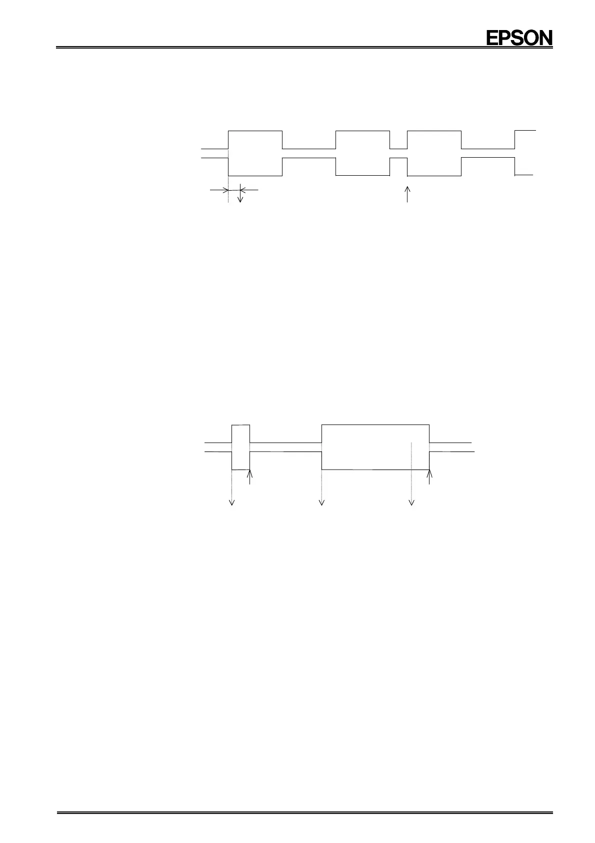
∗1) Pulse mode
A 2-Hz or 1-Hz clock pulse is output.
The relation between the clock pulse and the count operation is shown below.
/INTA pin
Overwrite seconds counter
CTFG bit
92µs (approx)
(Count up seconds)
Note 1: As is shown in the above diagram, the seconds register's count up operation occurs approximately
92 µs after the falling edge of the /INTA output. Therefore, if the clock's value is read immediately
after the output's falling edge, the read clock value may appear to be about one second slower than
the RTC module's clock value.
Note 2: When the seconds counter is overwritten, the counter for time values under one second is also
reset, which causes the /INTA level to go low ("L") again.
Note 3: When using the clock precision adjustment function, the periodic interrupt's cycle changes once
every 20 seconds.
During pulse mode:
The period during which the output pulse is low can be adjusted backward or forward up to
±3.784 msec.
(For example, the duty for the 1-Hz setting can be adjusted ±0.3784% from 50%.)
∗2) Level mode
Select among four interrupt cycles: one second, one minute, one hour, or one month.
Counting up of seconds occurs in sync with the falling edge of the interrupt output. The following is a timing
chart when a one-second interrupt cycle has been set.
/INTA pin
(Count up seconds)
Write 0 to CTFG
CTFG bit
(Count up seconds)
(Count up seconds)
Write 0 to CTFG
Note: When using the clock precision adjustment function, the periodic interrupt's cycle changes once every
20 seconds.
During level mode
A one-second period can be adjusted backward or forward up to ±3.784 msec.