RX
-
8025
SA
/
NB
Page - 23 ETM10E-04
8.8. Reading/Writing Data via the I
2
C Bus Interface
8.8.1. Overview of I
2
C-BUS
The I
2
C bus supports bi-directional communications via two signal lines: the SDA (data) line and SCL (clock) line. A
combination of these two signals is used to transmit and receive communication start/stop signals, data transfer
signals, acknowledge signals, and so on.
Both the SCL and SDA signals are held at high level whenever communications are not being performed. The
starting and stopping of communications is controlled at the rising edge or falling edge of SDA while SCL is at high
level. During data transfers, data changes that occur on the SDA line are performed while the SCL line is at low level,
and on the receiving side the data is captured while the SCL line is at high level. In either case, the data is
transferred via the SCL line at a rate of one bit per clock pulse. The I
2
C bus device does not include a chip select pin
such as is found in ordinary logic devices. Instead of using a chip select pin, slave addresses are allocated to each
device and the receiving device responds to communications only when its slave address matches the slave address
in the received data.
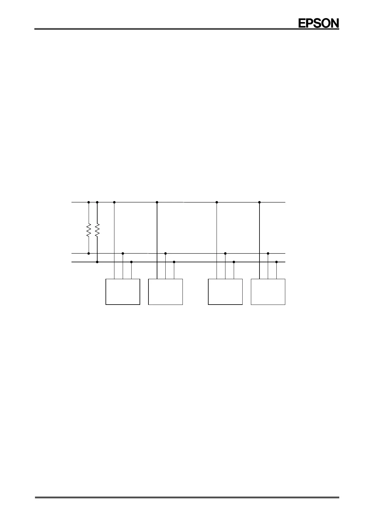
8.8.2. System configuration
All ports connected to the I
2
C bus must be either open drain or open collector ports in order to enable AND
connections to multiple devices.
SCL and SDA are both connected to the V
DD
line via a pull-up resistance. Consequently, SCL and SDA are both
held at high level when the bus is released (when communication is not being performed).
Master
Transmitter/
Receiver
Slave
Transmitter/
Receiver
Other I
C bus device CPU, etc. RX - 8025
SDA
SCL
V
DD
Master
Transmitter/
Receiver
Slave
Transmitter/
Receiver
Any device that controls the transmission and reception of data is defined as a master device and any device that is
controlled by a master device is defined as a slave device.
Also, any device that transmits data is defined as a transmitter and any device that receives data is defined as a
receiver.
In the case of this RTC module, controllers such as a CPU are defined as master devices and the RTC module is
defined as a slave device. When a device is used for both transmitting and receiving data, it is defined as either a
transmitter or receiver depending on these conditions.
Note
When a crystal oscillation is stopping, RX-8035 cannot output ACK signal in I2C access.
Therefore,
In initial-power-ON, please access RX-8035, after crystal oscillation started.
Internal crystal start-up time are 1sec. (Max.)