RX
-
8025
SA
/
NB
Page - 6 ETM10E-04
8.2. Description of Registers
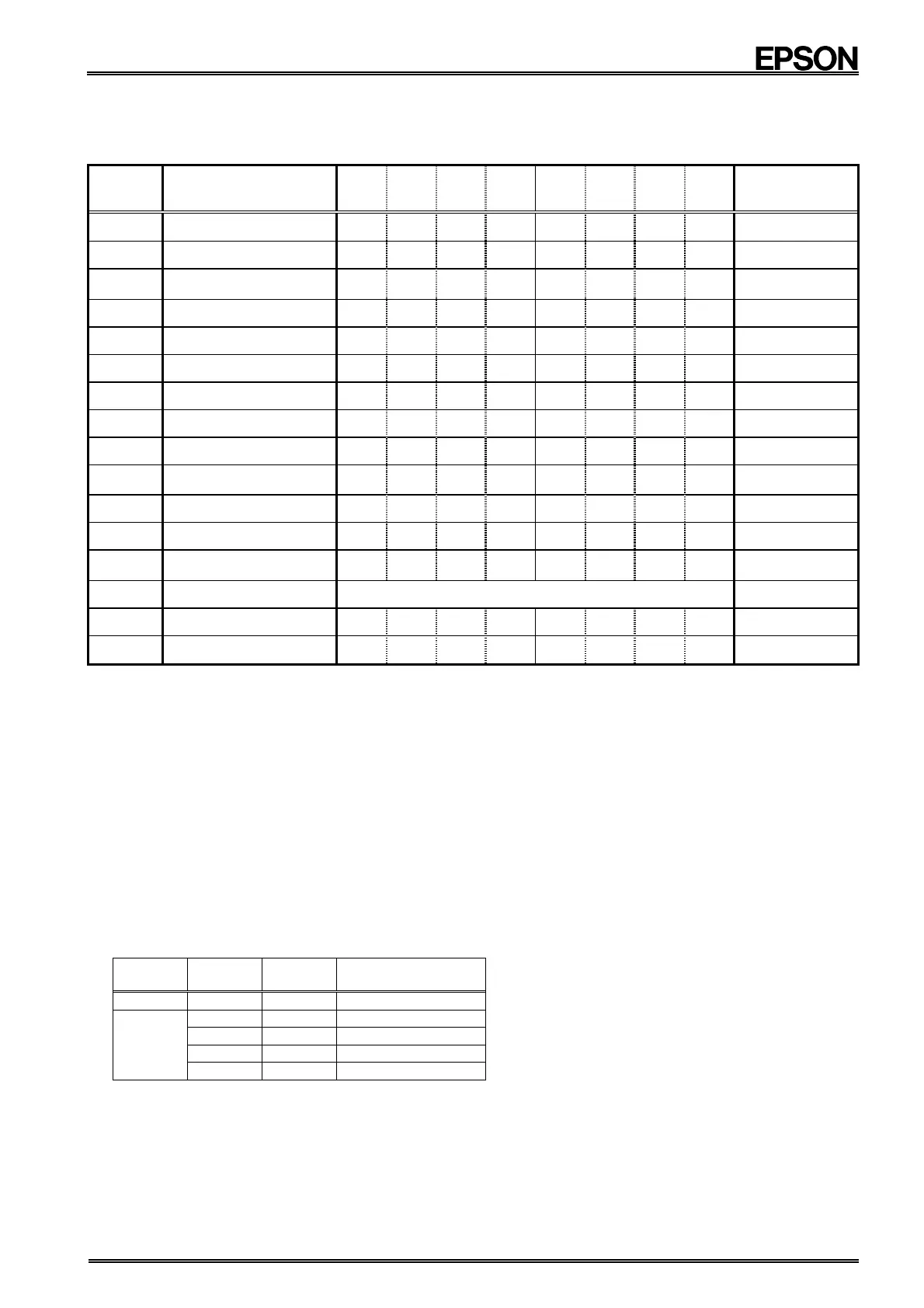
8.2.1. Register table
Address
Function bit 7
bit 6
bit 5
bit 4
bit 3
bit 2
bit 1
bit 0
note
0 Seconds
S40
S20
S10
S8 S4 S2 S1
∗5
1 Minutes
M40
M20
M10
M8 M4 M2 M1
∗5
2 Hours
H20
P , /A
H10
H8 H4 H2 H1
∗5
3 Weekdays
W4 W2 W1
∗5
4 Days
D20
D10
D8 D4 D2 D1
∗5
5 Months C
MO10
MO8
MO4
MO2
MO1
∗4, ∗5
6 Years Y80
Y40
Y20
Y10
Y8 Y4 Y2 Y1
−
7 Digital Offset
TEST
F6 F5 F4 F3 F2 F1 F0
∗4
8 Alarm_W ; Minute
WM40
WM20
WM10
WM8
WM4
WM2
WM1
∗5
9 Alarm_W ; Hour
WH20
WP,/A
WH10
WH8
WH4
WH2
WH1
∗5
A Alarm_W ; Weekday
WW6
WW5
WW4
WW3
WW2
WW1
WW0
∗5
B Alarm_D ; Minute
DM40
DM20
DM10
DM8
DM4
DM2
DM1
∗5
C Alarm_D ; Hour
DH20
DP , /A
DH10
DH8
DH4
DH2
DH1
∗5
D Reserved Reserved
∗3
E Control 1
WALE
DALE
/12 , 24
/CLEN2
TEST
CT2
CT1
CT0
∗1, ∗2, ∗6
F Control 2
VDSL
VDET
/XST
PON
/CLEN1
CTFG
WAFG
DAFG
∗1, ∗6
Caution points:
∗1.
The PON bit is a power-on reset flag bit.
The PON bit is set to "1" when a reset occurs, such as during the initial power-up or when recovering from a
supply voltage drop. At the same time, all bits in the Control 1 and Control 2 registers except for the PON and /
XST bits are reset to "0".
Note: At this point, all other register values are undefined, so be sure to perform a reset before using the module.
Also, be sure to avoid entering incorrect date and time data, as clock operations are not guaranteed when
the time data is incorrect.
∗2.
The TEST bit is used by the manufacturer for testing. Be sure to set "0" for this bit.
∗3.
Read data from address-D are always "00", and The write access to address-D are invalid.
∗4.
All bits marked with a " 0
" in the above table should be set as "0". Their value when read will be "0".
∗5.
All bits marked with "
" are read-only bits. Their value when read is always "0".
∗6.
When PON bit became 1 because power-on reset function worked, /CLEN1 and /CLEN2 bit become 0.
When /CLEN1 and /CLEN2 bit become 1 even if FOE input is "H", FOUT output stops.
FOE
input
/CLEN1
bit
/CLEN2
bit
FOUT
output
L
Χ Χ OFF ( " L " )
H
0 0 32.768 kHz
0 1 32.768 kHz
1 0 32.768 kHz
1 1
OFF ( " L " )
' Χ ' Don't care.