RX
-
8025
SA
/
NB
Page - 17 ETM10E-04
8.5. Alarm W function
The Alarm W function generates interrupt signals (output via the /INTB pin) that correspond to specified days,
hours, and minutes.
For description of the Alarm D function, which supports only hour and minute data, see "8.6. Alarm D Function".
Multiple day settings can be selected (such as Monday, Wednesday, Friday, Saturday, and Sunday).
A polling function is also provided to enable checking of each alarm mode by the host.
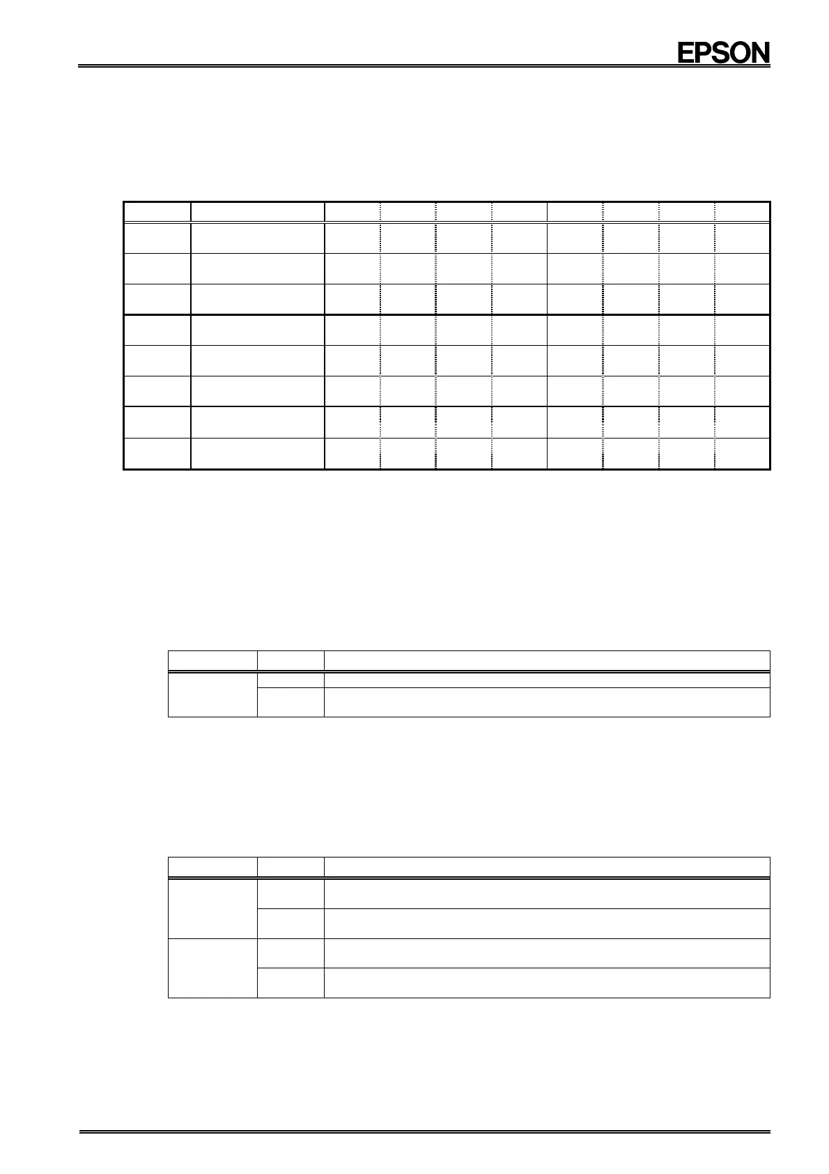
8.5.1. Related registers
Address
Function bit 7 bit 6 bit 5 bit 4 bit 3 bit 2 bit 1 bit 0
1
Minutes
M40 M20 M10 M8 M4 M2 M1
2
Hours
H20
P, /A
H10 H8 H4 H2 H1
3
Days
W4 W2 W1
8
Alarm_W ; Minute
WM40
WM20
WM10
WM8 WM4 WM2 WM1
9
Alarm_W ; Hour
WH20
WP, /A
WH10
WH8 WH4 WH2 WH1
A
Alarm_W ; Day
WW6
WW5
WW4
WW3
WW2
WW1
WW0
E
Control 1
WALE
DALE
/12, 24
/CLEN2
TEST CT2 CT1 CT0
(Default)
(0)
(0)
(0)
( 0 ) ( 0 ) (0) (0) (0)
F
Control 2
VDSL VDET / XST PON /CLEN1
CTFG
WAFG
DAFG
(Default) (0) (0)
(−)
( 1 ) ( 0 ) (0)
(0)
(0)
∗1) The default value is the value that is read (or is set internally) after the PON bit has been set to "1," such as after powering up from 0 V or
recovering from a supply voltage drop.
∗2) "○" indicates write-protected bits. A zero is always read from these bits.
∗3) "−" indicates undefined status.
• When the Alarm_W setting matches the current time, /INTB pin is set to "L" and the WALE bit is set to "1".
Note: If the current date/time is used as the Alarm_W setting, the alarm will not occur until the counter counts up
to the current date/time (i.e., an alarm will occur next time, not immediately).
• During 24-hour clock operation, the "Alarm_W ; Hours" register's bit 5 (WH20, WP, /A) functions as WH20
(two-digit hour display), and during 12-hour clock operation it functions as an AM/PM indicator.
• When the Alarm_W function's day values (WW6 to WW0) are all "0" Alarm W does not occur.
1) WALE bit
This bit is used to set up the Alarm W function (to generate alarms matching day, hour, or minute settings).
WALE Data Description
Write / Read
0 Alarm_W, match comparison operation invalid
∗ Default
1
Alarm_W, match comparison operation valid (/INTB = "L" when
match occurs)
∗ When using the Alarm W function, first set this WALE bit value as "0," then stop the function. Next, set
the day, hour, minute, and the WAFG bit. Finally, set "1" to the WALE bit to set the Alarm W function as
valid. The reason for first setting the WALE bit value as "0" is to prevent /INTB = "L" output in the event
that a match between the current time and alarm setting occurs while the alarm setting is still being made.
2) WAFG bit
This bit is valid only when the WALE bit value is "1". When a match occurs between the Alarm_W setting and
the current time, the WAFG bit value becomes "1" approximately 61 µs afterward. (There is no effect when the
WALE bit becomes "0".)
The /INTB = "L" status that is set at this time can be set to OFF by writing a "0" to this bit.
WAFG Data Description
Write
0
/INTB pin = OFF (Hi-z)
∗ Default
1
Setting prohibited (do not set this bit value, even though it has no
effect)
Read
0
Alarm_W time setting does not match current time
(This bit's value is always "0" when the WALE bit's setting is "0")
∗ Default
1
Alarm_W setting matches current time
(Result is that bit value is held until cleared to zero)
∗ When a "0" is written to the WAFG bit, provisionally the WAFG bit value is "0" and the /INTB pin status is
OFF (Hi-z). However, as long as the WALE bit value is "1" the Alarm W function continues to operate, and
Alarm W occurs again the next time the same specified time arrives. You can stop Alarm W from
occurring by writing "0" to the WALE bit to set this function as invalid.