RX
-
8025
SA
/
NB
Page - 26 ETM10E-04
8.8.6. I
2
C
bus's basic transfer format
• The write/read steps are illustrated below.
Master is transmitter (sending side),
RTC is receiver (receiving side)
Master is receiver (receiving side)
、
RTC is transmitter (sending side)
S
START condition,
sent by Master
Sr
RESTART condition,
sent by Master
P
STOP condition,
sent by Master
A
Confirmation response from
Master
A
Confirmation response from
RTC
/A
Master does not respond
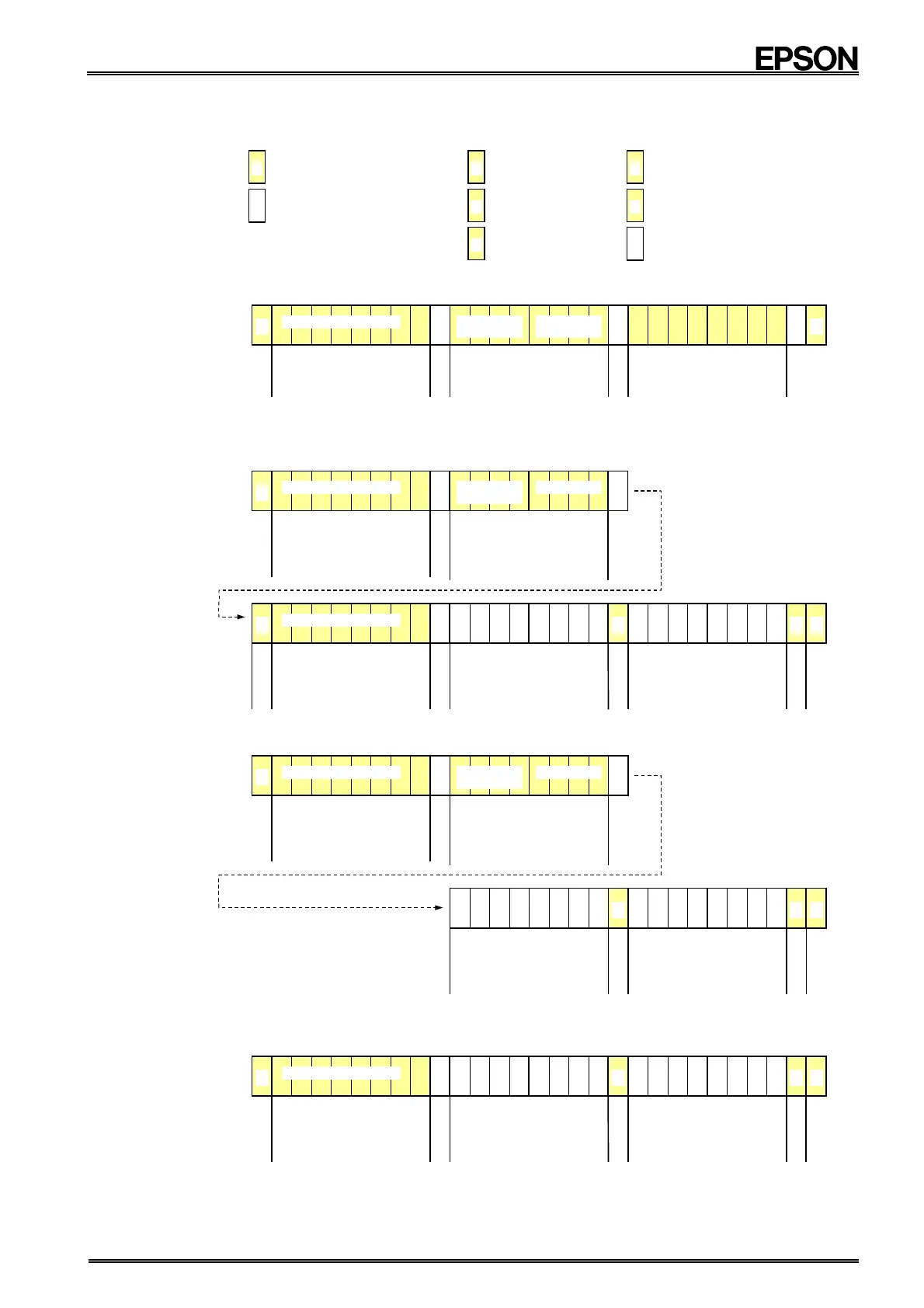
1) Write via I
2
C
bus
• The steps for writing via the I
2
C
bus are shown below.
bit
7
bit
6
bit
5
bit
4
bit
3
bit
2
bit
1
bit
0
S
A
Slave address
+
write specification
0 h ∼
∼∼
∼ F h (∗
∗∗
∗1)
0 h (∗
∗∗
∗1)
Address + transfer mode specification
∗
1) Specifies the write start address.
∗
2)
Specifies the write mode (= 0h fixed).
0
1
1
0
0
1
0
Write
0
Slave address (7 bits)
A
Write data
A
P
2) Read via I
2
C
bus
(1) Standard read method for I
2
C
bus
• The steps for standard reading of the I
2
C bus are shown below.
S
A
Slave address +
write specification
∗
This "write" is the writing of the read
start address, which occurs during a
read operation.
0
1
1
0
0
1
0
Write
0
Slave address (7 bits)
A
Sr
A
Slave address +
read specification
∗
Indicates next byte will be read.
0
1
1
0
0
1
0
Read
1
Slave address (7 bits)
R
e
s
t
a
r
bit
7
bit
6
bit
5
bit
4
bit
3
bit
2
bit
1
bit
0
bit
7
bit
6
bit
5
bit
4
bit
3
bit
2
bit
1
bit
0
Data read (2)
∗ Address auto incrementation function
is used to add one to the last address
read to set the start address for the
next data to be read.
P
A
/A
N
o
A
C
K
Data read (1)
∗ Data is read from the specified
start address.
Standard Read mode
•
Transfer mode setting = 0h
0
0
0
0
0 h
∼
∼∼
∼
F h
Address and transfer mode settings
∗
1)
Specifies the read start address.
∗
2)
Specifies the Standard Read
mode (= 0h)
(2) Simplified read method
• This RTC module also provides a special read method that uses fewer read steps.
bit
7
bit
6
bit
5
bit
4
bit
3
bit
2
bit
1
bit
0
S
A
Slave address + write specification
∗
This "write" is the writing of the read
start address, which occurs during a
read operation.
0
1
0
0
0 h ∼
∼∼
∼ F h
Transfer mode
Address and transfer mode settings
∗
1)
Specifies the read start address.
∗
2)
Specifies the Simplified
Read mode (= 4h)
0
1
1
0
0
1
0
Write
0
Slave address (7 bits)
A
bit
7
bit
6
bit
5
bit
4
bit
3
bit
2
bit
1
bit
0
Data read (2)
∗
Address auto incrementation function
is used to add one to the last address
read to set the start address for the
next data to be read.
P
A
/A
N
o
A
C
K
Simplified Read mode
•
Transfer mode setting = 4h
Data read (1)
∗
Data is read from the specified
start address.
(3) Read method from address Fh, with no specified start address for read operation
• Only when reading from address Fh (Fh → 0h → 1h → 2h, etc.) can a read operation be performed
without specifying the read start address or the transfer mode.
S
A
Slave address +
read specification
∗
Indicates next byte will be read.
0
1
1
0
0
1
0
Read
1
Slave address (7 bits)
bit
7
bit
6
bit
5
bit
4
bit
3
bit
2
bit
1
bit
0
bit
7
bit
6
bit
5
bit
4
bit
3
bit
2
bit
1
bit
0
Data read (2)
∗
The address auto incrementation
function is used to read data from
address Fh + 1 (= 0h).
P
A
/A
N
o
A
C
K
Data read (1)
∗
Since no address is specified, data is
read from address Fh.
∗ The above steps are an example of transfers of one or two bytes only. There is no limit to the number of bytes
transferred during actual communications. (However, the transfer time must be no longer than 0.5 seconds and
access to the Address Dh (Reserved) register is prohibited.)