1) VLOW bit (Time Stamp VLOW)
This bit records the comparison result of V
BAT
vs V
LOW
at the moment of event.
Table 61 VLOW bit (Time Stamp VLOW)
2) VCMP bit (Time Stamp VCMP)
This bit records the comparison result of V
DD
vs V
BAT
(VCMP status) at the moment of event.
Table 62 VCMP bit (Time Stamp VCMP)
3) VDET bit (Time Stamp VDET)
This bit records the comparison result of V
DD
vs V
DET1
at the moment of event.
Table 63 VDET bit (Time Stamp VDET)
4) XST bit (Time Stamp X’tal Oscillation Stop)
This bit records either internal Crystal oscillation stop or not stop at the moment of event.
Table 64 XST bit (Time Stamp X’tal Oscillation Stop)
Normal Internal Crystal oscillation
Internal Crystal oscillation stops
14.8.6. RTC internal event triggered time stamp, multiple times stamp
In addition to EVIN pin input triggered , the RTC time stamp can be triggered by internal event.
Also, time stamp events are continuously recoded into RAM up to maximum 8 times.
To avoid unwanted timestamp event, ETS register should be reset to 0 before reading time stamp data (2hf ~ 29h, 40h ~ 47h).
(Refer to Figure36)
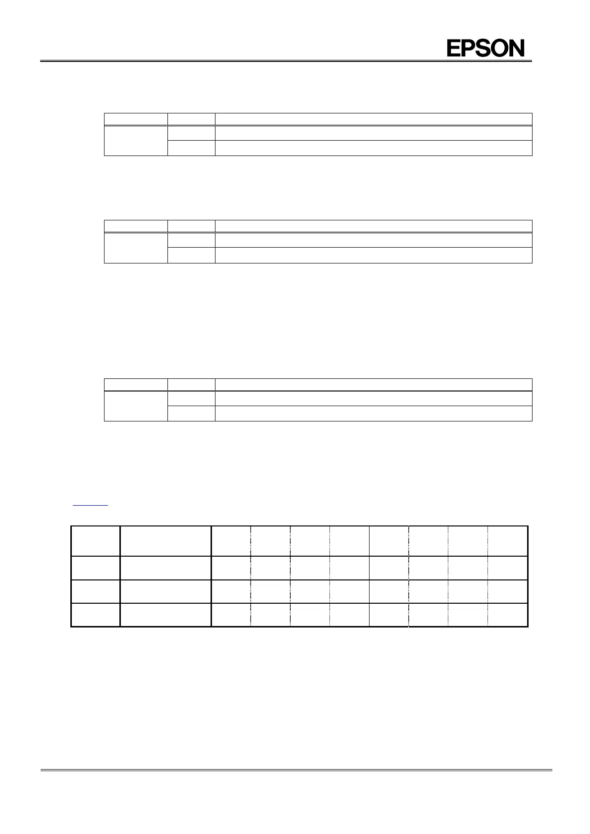
Table 65 Related register for internal event triggered time stamp, multiple times stamp