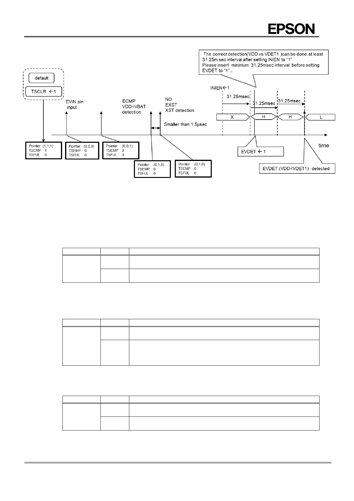
Figure 37 Careful timing process when RTC internal status trigger is used for time stamp
(2) Multiple time stamp is available with following registers management.
The record area (40h 7Fh) all the time stamp is recorded except 1/1024 sec, WEEK.
1) TSRAM bit
This bit control RAM (40h7Fh) the usage time stamp recording or normal RAM.
Table 70 TSRAM bit (Time Stamp Clear)
40h~7Fh is used a normal (Read/Write enable)
Time stamp data is recorded into 20h-28h at event timing.
40h~7Fh is used a time stamp recording memory. (Read/Write enable)
User can modify directly RAM data via I
2
C if necessary.
2) TSCLR bit (Time Stamp Clear)
The operation of writing “1” to this bit makes address 36h clear to initialize and this bit be reset to “0” automatically.
Time stamp function should be disenabled by resetting ETS to “0” before this operation (Time stamp clear).
Table 71 TSCLR bit (Time Stamp Clear)
Invalid (writing “0” will be ignored)
Initializing address 36h register.
TSFUL: 0, TSEMP: 1
TSAD2: 1, TSAD1: 1, TSAD0: 1
pointer (1,1,1)
3) EISEL bit (Event Interrupt Select)
This bit controls time stamp event interrupt selection.
Table 72 EISEL bit (Event Interrupt Select)
Every time stamp event triggering makes interrupt output.
In case of 8 times record (of time stamp) interrupt output occurs.