SE Group Confidential (Related Staff Only)
Adjustment Details of Adjustments 44
SC-P600 Revision D
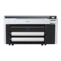
7. Press the standard positions to the direction of the back of the printer until hitting the printer.
Figure 2-7. Setting the PF Roller Adjustment Jig (2)
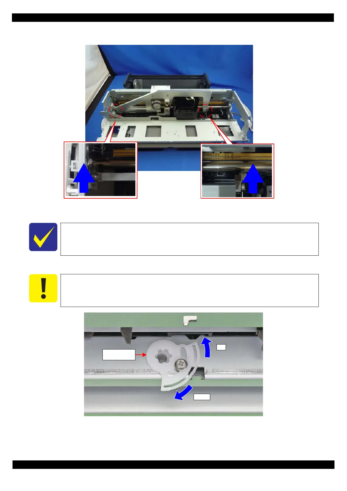
8. Turn the Center Support Bushing Cam so that the long hand position is to between the standard value.
Figure 2-8. Positional Relationship between Center Support Bushing Cam and the Dial Gage
The standard range of the PF Roller Shaft Center Support Position Adjustment is as follows:
Standard value: -10 μm - 40 μm
Make sure that the position of the short hand is the same as at “0” adjustment.
down
up
Center Support
Bushing Cam