SE Group Confidential (Related Staff Only)
Adjustment Details of Adjustments 52
SC-P600 Revision D
8. Lower the gear of the Parallelism Adjust Bushing on the left side of the frame stepwise, and confirm
continuity. When continuity is confirmed, define the position where the gear was raised one step up from the
continuity position (where continuity is lost) as the left side PG position. Move the Parallelism Adjust
Bushing at least twice to confirm that the continuity position and the noncontinuity position are the same.
9. To set the PG position to “5”, turn the PG Cam on right end of the Carriage Shaft counterclockwise (CCW)
so that the point marked “5” faces down. (See Figure 2-17.)
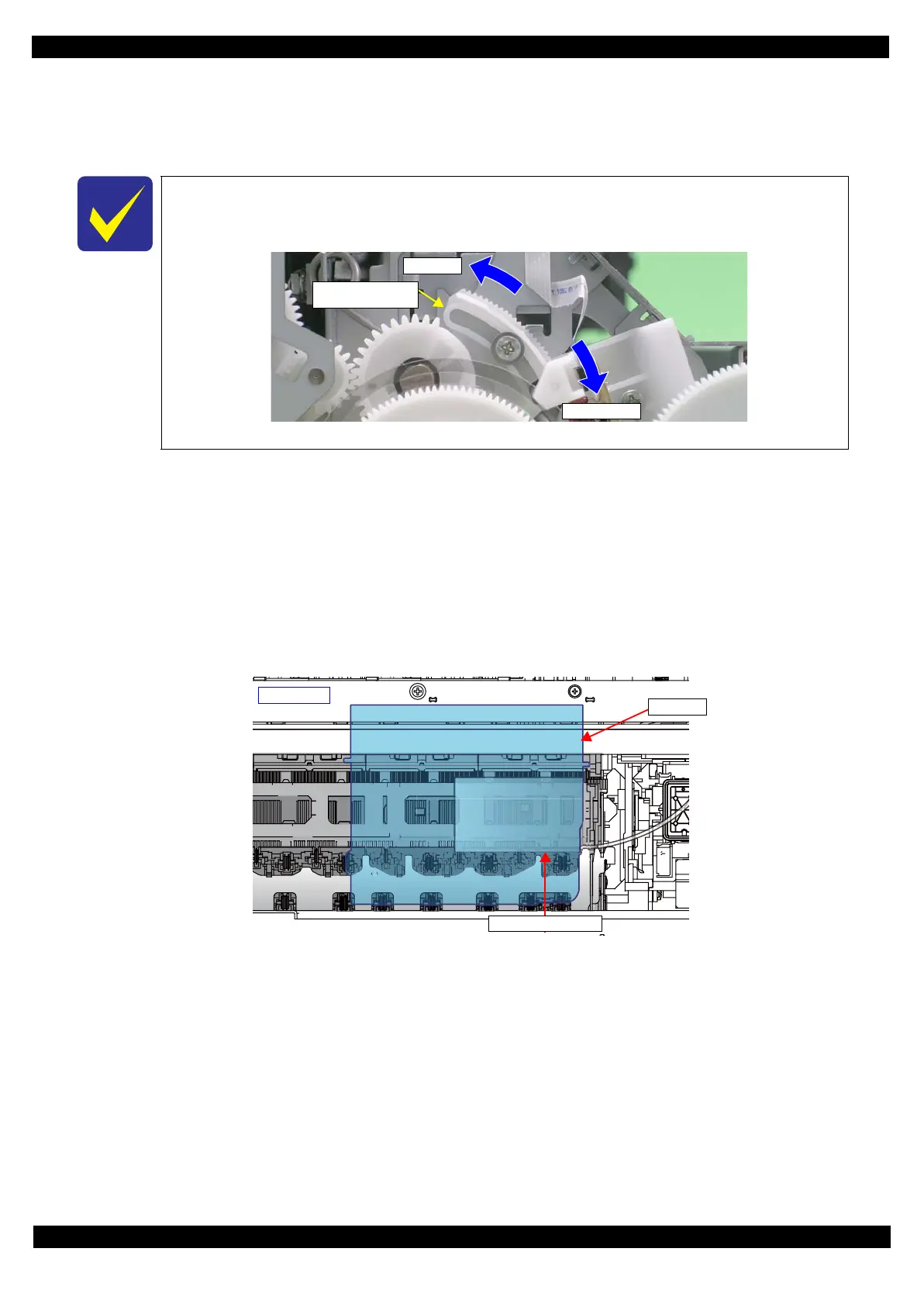
10. With its conductor connection portion down, set the adjustment gauge in the specified position (on the right
side of the Front Paper Guide Assy).
Setting Position
Rear direction: Align the rear end of the gauge with the Driven Roller Shaft of the Upper Paper Guide.
Right direction:Align the right end of the gauge with the position shown in Figure 2-20.
11. Move the CR Unit onto the adjustment gauge.
Moving position
Align the right end of the gauge with the right end of the CR Unit.
Figure 2-20. Setting the Adjustment Gauge
12. To set the PG position to “0”, turn the PG Cam on right end of the Carriage Shaft clockwise (CW) so that the
point marked “0” faces down. (See Figure 2-17.)
13. As in
Step 8
, move the Parallelism Adjust Bushing on the right side of the frame to set the right side PG position.
14. Set the PG position to “5”.
15. Set the adjustment gauge on the left side of the Front Paper Guide Assy.
16. Move the CR Unit onto the left side adjustment gauge.
17. Return the PG position to “0”.
18. Check continuity again at the PG position on the left side. If the PG position is not out of position, tighten the
Parallelism Adjust Bushing with the screws to complete the adjustment. If it is out of position, repeat the
adjustment procedure from Step 8.
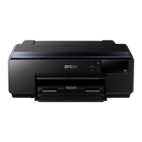
The following figure shows the states of the Adjust Parallel Bushing of the left side of the
frame and the PG.
(This also applies to the Adjust Parallel Bushing on the right side of the frame.)
Figure 2-19. Relationship between Parallelism Adjust Bushing and PG
Narrower PG
Wider PG
Parallelism Adjust
Bushing
0-digit side
CR Unit
Adjustment Gauge