Epson WF-7520/7510/7010 series Revision A
Disassembly/Reassembly Detailed Disassembly/Reassembly Procedure for each Part/Unit 55
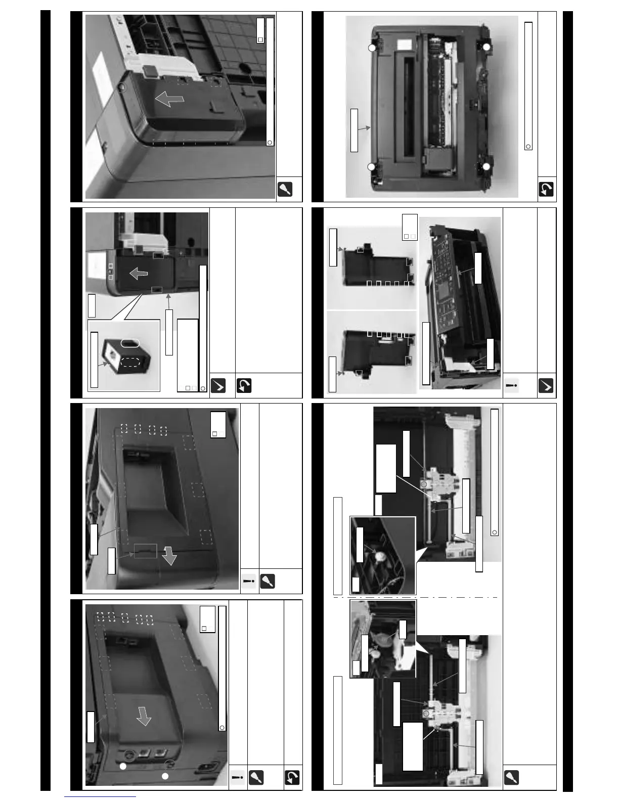
4.3 Detailed Disassembly/Reassembly Procedure for each Part/Unit
USB Cover (WF-7520/7510 series)
Be careful not to damage the hooks (x6) that secure the USB
Cover.
When removing the USB Cover, follow the procedure below.
1. Remove the screws (x2) that secure the USB Cover.
2. Release the hooks (x6) of the USB Cover by sliding it in the direction
of the arrow shown above, and then remove the USB Cover.
Tighten the screws in the order indicated in the figure above.
C.B.P-TITE SCREW 3x10 F/ZB-3C (6 ± 1 kgf·cm)
Hook
Rib
USB Cover
1
2
USB Cover (WF-7010 series)
Be careful not to damage the hooks (x6) that secure the USB
Cover.
When removing the USB Cover, follow the procedure below.
1. Lift the section A of the USB Cover using a flathead
screwdriver or a similar tool.
2. Slide it in the direction of the arrow to release the hooks (x6),
and then remove the USB Cover.
USB Cover
Section A
Hook
Rib
Waste Ink Tray Assy
For WF-7520/7010 series, the depth of the hole on the bottom of the printer
for the Waste Ink Tray Assy attachment differ because of the 2nd Bin Base
Assy, but the disassembly procedure is the same as that of WF-7510 series.
When installing the Waste Ink Tray Assy, follow the procedure below.
1. Align the ribs (x2) on both sides of the Waste Ink Tray Assy
with the grooves (x2) of the Frame Base Assy, and insert the
Waste Ink Tray Assy from the bottom of the Frame Base Assy.
2. Slide the Waste Ink Tray Assy in the direction of the arrow to
engage the dowels (x2) of the Waste Ink Tray Assy with the
positioning holes (x2) of the Frame Base Assy.
3. Secure the Waste Ink Tray Assy with the screw (x1).
C.B.P-TITE SCREW 3x10 F/ZB-3C (6 ± 1 kgf·cm)
Rib
Dowel and positioning hole
Frame Base Assy
Groove
Bottom
Waste Ink Tray Cover (WF-7520/7010 series)
When removing the Waste Ink Tray Cover, remove the screw (x1)
and slide the Waste Ink Tray Cover in the direction of the arrow to
release the hooks (x5).
Hook
C.B.P-TITE SCREW 3x10 F/ZB-3C (6 ± 1 kgf·cm)
Pickup Assy 1st / 2nd
When removing the Pickup Assy 1st / 2nd, follow the procedure below.
1. Release the Pickup Assy 1st / 2nd from the Pickup Escape Lever.
2. Remove the screws (x1 each) that secure the Pickup Assy 1st / 2nd.
3. Pickup Assy 1st: Release the hook of the Spur Gear 32 and remove the Spur Gear 32 from the Pickup Driven Shaft, and then pull out the shaft
from the hole of the Frame Base Assy, and remove the Pickup Assy 1st.
4. Pickup Assy 2nd: Remove the Pickup Driven Shaft from the Spur Gear 16, and remove the Pickup Assy 2nd from the 2nd Bin Base Assy.
Pickup Assy 1st
Pickup Driven Shaft
Pickup Escape Lever
The location where
the Pickup Escape
Lever interferes.
Pickup Assy 2nd
Pickup Driven Shaft
C.B.P-TITE SCREW 3x10 F/ZN-3C (6 ± 1 kgf·cm)
Pickup Assy 1st (WF-7520/7510/7010 series) Pickup Assy 2nd (WF-7520/7010 series)
Pickup Escape Lever
Bottom
The location where
the Pickup Escape
Lever interferes.
Housing Left/Housing Right (WF-7520/7510 series)
Be careful not to damage the hooks (x3 each) and ribs
(x5 each) that secure the Housing Left/Housing Right.
When installing the Housing Left, be careful no to catch the
Cover Open Sensor cable and Panel FFC.
When removing/installing the Housing Left/Housing Right, do it
with the Panel Unit open.
Cover Open Sensor cable
Panel Unit
Panel FFC
Housing Upper (WF-7520/7510 series)
Tighten the screws in the order indicated in the figure above.
C.B.P-TITE SCREW 3x10 F/ZN-3C (6 ± 1 kgf·cm)
1
2
3
4
Housing Upper