Do you have a question about the EqualLogic PS6500 and is the answer not in the manual?
Ensure sufficient space in the rack for a 4U chassis, which spans 12 post holes.
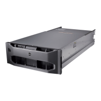
Remove the array chassis from the shipping box and place it on a sturdy surface. Unlock and release the bezel latch.
Remove the three power supply and cooling modules to lighten the array for easier rack installation.
Attach the left and right mounting rails to the appropriate rack posts using provided or suitable screws.
Extend telescoping sections of the rails, lift the chassis with assistance, and slide it onto the mounting rails carefully.
Unlock the chassis, pull the front panel out, and attach the chassis cover to the front rail flanges.
Handle disk drives carefully. Insert drives into slots with latches towards the rear, ensuring proper seating and latch engagement.
Fit the bezel into the chassis, push until it engages, and lock it using the bezel key.
Orient power supply modules with the socket towards the bottom, slide them into slots, and secure by closing the handles.
Attach cable management wire assemblies to the rear chassis flange and rack rails to organize cables.
| Model | PS6500 |
|---|---|
| Category | Storage |
| Drive Type | SAS, SATA |
| RAID Levels Supported | RAID 5, RAID 6, RAID 10, RAID 50 |
| Management Software | EqualLogic Group Manager |
| Snapshot Support | Yes |
| Replication Support | Yes |
| Thin Provisioning | Yes |
| Controller Redundancy | Yes |
| Storage Type | SAN |
| Host Interfaces | 1 Gigabit Ethernet |
| Operating Temperature | 10°C to 35°C |