with a shaft diameter that does not t to the collet.
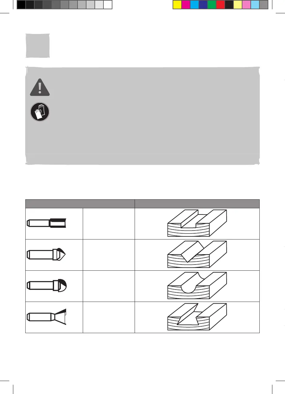
Router bits are available in various shapes and sizes. Below is only a short overview
of the most commonly shapes. Ask the store for more choices.
Inserting (Fig. A)
1. Put the router upside down with its standing feet (4) on a stable work bench.
2. Press the spindle lock (14) and turn the clamp nut with collet (20) slowly until the
spindle lock (14) engages. Hold the spindle lock (14) in position (Fig. A, step 1).
3. Loosen the clamp nut with collet (20) anticlockwise with the wrench (27) (Fig. A,
step 2).
4. For bits with 1/2 inch (for UK) or 12mm (for EU) shank, insert a suitable router bit
(22) into the clamp nut with collet (20) directly until “K”-mark and/or 25mm at least.
(Fig. A, step 3).
5. For other bits, insert the suitable collet (23) into the clamp nut with collet (20) fully,
then insert the router bit (22) into the collet (23) until “K”-mark and/or 25mm at
least. (Fig. A, step 3).
6. Tighten the clamp nut with collet (20) clockwise with the wrench (27).
7. Release the spindle lock (14) and make sure that the spindle can rotate freely.
NOTE: Choose the correct router bit according to the desired operation.
Before use, please always ensure the router bit is properly attached and
free of damage.
Removing (Fig. A)
1. Put the router upside down with its standing feet (4) on a stable work bench.
2. Press the spindle lock (14) and turn the clamp nut with collet (20) slowly until the
spindle lock (14) engages. Hold the spindle lock (14) in position (Fig. A, step 1).
3. Loosen the clamp nut with collet (20) anticlockwise with the wrench (27) (Fig. A,
step 2).
4. Remove the router bit (22) and collet (23) if necessary and keep the small parts
safe, especially the removed collet (23).
5. Attach the clamp nut with collet (20) with normal nger force.
03
Parallel guide
Attach the parallel guide from the left or right side to perform cuts parallel to the left or
right edge of the workpiece.
Attaching (Fig. B, C)
1. Loosen the guide base xing knobs (9b x2) and adjustment guide xing knobs (9d
x2) anticlockwise slightly and ensure that the ends of guide rods (9h x2) are ush
to the outer side of the adjustment guide assembly (9e) (Fig. B).
2. Fix the guide rods (9h x2) in the adjustment guide assembly (9e) by tightening the
adjustment guide xing knobs (9d x2) clockwise.