25 / 62
3 • Description of the Controls
80110-201_V24169
2022-01
Chapter 3
Description of the Controls
Controls
The APC 2 itself represents a separate socket module within the VIO system as a whole.
It must therefore only be used in connection with a VIO electrosurgical system, as the
central controls are found there, including those for the APC 2. For operation of the
APC 2 the following controls and options are thus basically available:
• the controls of the VIO electrosurgical system (see also relevant section)
• the controls on the sockets of the APC 2
• the footswitches for VIO.
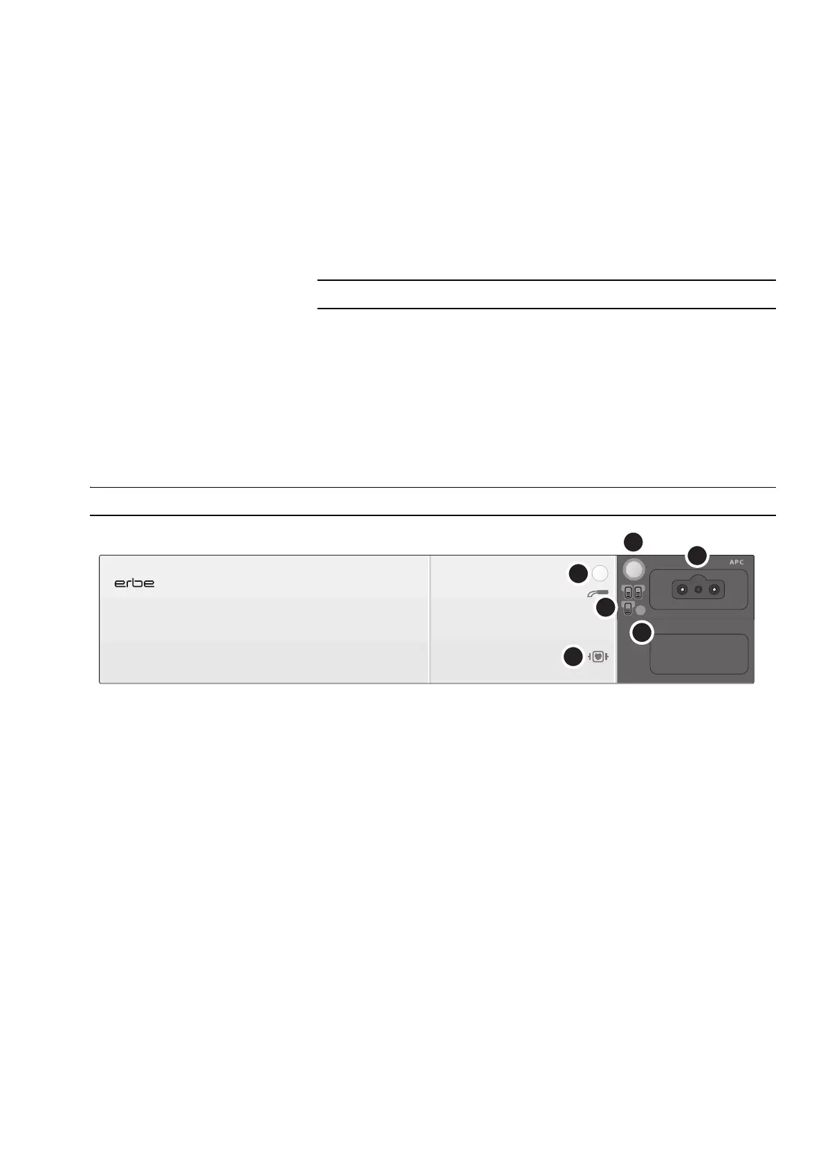
Controls on the front panel
Fig. 3-1
(1) Purge button
Before the instrument can be activated for the first time, it must first be purged with
argon. The Purge button only functions for the socket whose Focus button is lit up.
In the service programs of the VIO system, a technician can make the appropriate set-
ting according to whether the APC instrument is to be automatically purged with argon
when it is connected to the APC socket.
(2) Focus button for APC socket
If a Focus button next to the socket is pressed, the functions of the socket and the set-
ting of the functions will be shown in the display.
(3) Footswitch indicator lights
The footswitch symbol lights up when the respective footswitch is assigned to the
socket.
(4) APC socket
Plug the FiAPC connector of the instrument into this socket.
(5) CF icon
The unit conforms to the requirements of Type CF (Cardiac Float) and is protected
against the effects of a defibrillator discharge.
(6) ECB indicator light
This light turns up red when there is no ECB connection between the APC and the elec-
trosurgical unit.
 Loading...