GB-13
GB
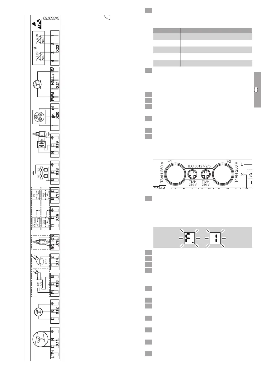
Internal connection diagram
LN LN L
LT LV
+T
–+V
mA
V12
LLiN
12 +
0 V
D – 49018 Osnabrück, Germany
ACU
Press the RESET button to reset. The unit then
reverts to the last operating mode selected.
▷ Possible faults
Display Fault type
F
Flame fault
A
Air fault
C
Temperature fault
E
Electronics fault
U
Other possible faults
4 If the burner control unit does not respond even
though all the possible faults have been rectified
as described below, contact your supplier.
? Fault
! Cause
• Remedy
? The 7-segment display has gone out despite
the voltage supply being OK?
! Fuse F2 is defective.
• Check the fuse contacts.
There is a spare fuse directly next to the fuse
holder.
Important! Fit the correct fuse for 4A.
LN LN L
LT LV
+T
–+V
mA
V12
LLiN
12 +
0 V
D – 49018 Osnabrück, Germany
ACU
? Fault code F. and 1 flash alternately?
On burner start-up, the burner control unit has
not detected a flame during the safety time. Sev-
eral automatic start-up attempts will be com-
pleted if a restart has been programmed.
! Inadequate inlet pressure available.
• Check the inlet pressure.
! Ignition is not working properly.
• Check the connection of the ignition cables for
damage or moisture. The spark plug must be
fitted correctly.
• Check the ignition spark acoustically during the
3-second ignition time from the burner fan side.
• Clean the ignition electrode.
• Check the ignition transformer and replace it if
necessary.
! Poor flame signal due to incorrect burner adjust-
ment.
• Readjust the CO
2
value, see page9 (Adjust-
ing the heater).
! Poor flame signal due to dirty or badly connected
ionization electrode.
• Check the ionization electrode and clean it with
fine abrasive paper if necessary.
Main fan
Burner fan
230 V
Not used
Not used
Ionization
WT Klixon
(temperature limiter)
Pressure switch for air
(vane not used)
Valves
Ignition
Status indicator
Burner fan
eSTB2
(temperature sensor)