41
3.9 RTD SIMULATION
NOTE: The instrument will operate in accordance to the selected
temperature standard (IPTS-68 or ITS-90) (see paragraph
"2.3 INSTRUMENT CONFIGURATION").
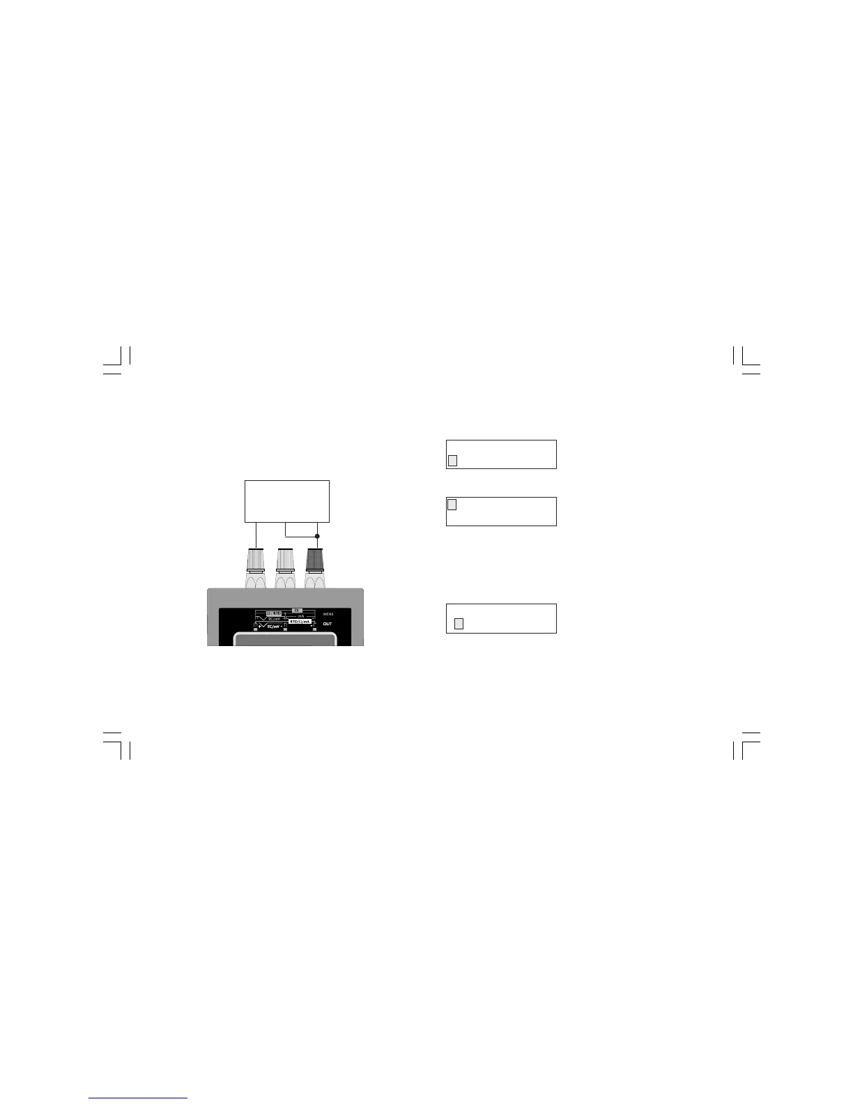
CONNECTION FOR RTD SIMULATION
NOTE: the measuring current must be higher than 100 mA and
lower than 2 mA and the polarity must be equal to the indication
shown in the drawing otherwise the instrument will generate an
error message (see chapter "ERROR MESSAGES").
HOW TO SIMULATE AN RTD SENSOR
Push OUT push-button; the display will show the following:
By pushing s or t push-button, select the "RTD" sensor.
Push the FUNC push-button; the display will show:
By pushing s or t push-button, select the desired RTD type (e.g.
Ni100).
NOTE: when ITS-90 is selected, the RTD type Ni 100 is not
available so that the instrument will show this RTD with small
letters and it does not allow to select it.
Push the FUNC push-button; the display will show the following:
Depressing s or t push-button, select the desired engineering
unit (e.g. °C).
OUT
TC RTD mA mV
Pt100 Ni100
Ohm
+
-
RTD
MEASURING
DEVICE
ENGINEERING UNIT
°C °F
M20-e-3.p65 7/9/01, 2:40 PM41
 Loading...