Do you have a question about the ero electronic DPS and is the answer not in the manual?
Details on minimum spacing and packing for horizontal instrument mounting.
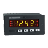
Overview of the DPS digital panel indicators and their features.
Detailed technical specifications including case, front panel, dimensions, and power supply.
Explains available optional features like communication interface and auxiliary power supply.
Explains the instrument's coding system for model, power supply, inputs, alarms, and options.
Describes the identification and abridged labels on the instrument for serial and model numbers.
Instructions for selecting a mounting location and physically installing the instrument.
Comprehensive guide for connecting power and input/output signals to the instrument.
Identifies and describes the components on the instrument's front panel.
Instructions for configuring the instrument's internal settings.
Step-by-step guide for configuring parameters via the front panel interface.
Lists and explains various configurable parameters like input type, TC type, and engineering units.
Steps to prepare the instrument for operation after configuration.
Instructions for normal operation of the instrument.
Procedure for manually resetting alarms if configured as latched.
Guide to setting or modifying alarm thresholds based on safety lock configuration.
How to use the hold function to stop data acquisition and freeze the displayed value.
Specifies the required DIP switch settings for calibration mode.
Essential environmental and procedural guidelines for accurate calibration.
Detailed instructions for calibrating the instrument's various input and output functions.
Procedure for loading the default parameter sets into the instrument.
Lists the default values for configuration parameters.
Lists default calibration parameters for verification, not actual calibration.
Lists the default parameters used in operative mode.
Describes how the instrument indicates signals outside the configured range.
Explains how the instrument detects and indicates an open input circuit condition.
General information on how the instrument performs diagnostics and displays error messages.
Detailed list of error codes, their causes, and suggested remedies.
| Brand | ero electronic |
|---|---|
| Model | DPS |
| Category | Measuring Instruments |
| Language | English |