49
C 6 - TC, mV INPUT MINIMUM RANGE VALUE
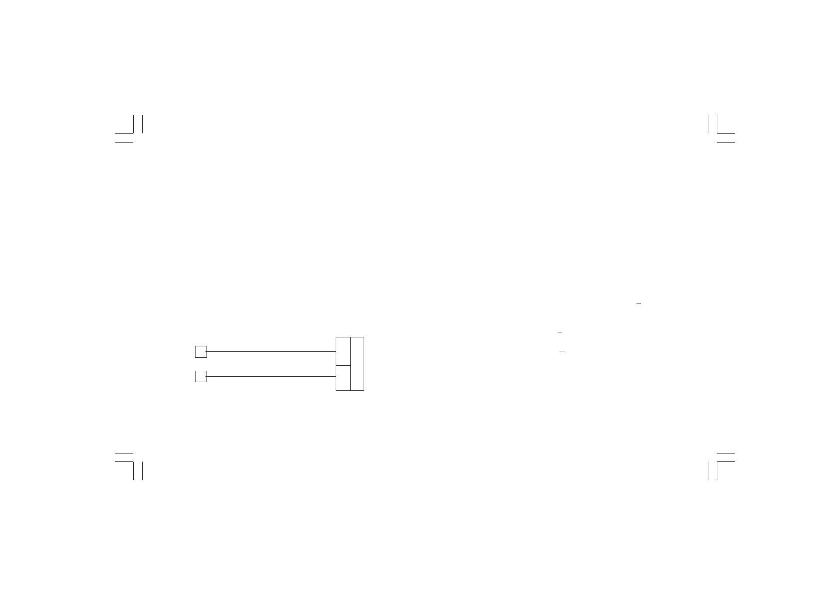
a) Provide connections between calibrator and instrument under
test as shown in Fig. 5.5.
b) The numerical display will show "OFF", while "C 6" will appear on
the alphanumerical display.
c) Set calibrator to 0.000 mV. Push ▲ pushbutton, the display will
change to "ON".
d) After few seconds, start calibration by pushing F pushbutton,
the display will blank and only the decimal point will appear on
the display.
At the end of this calibration routine, the instrument will go to the
next parameter.
Fig. 5.5
C 7 -TC, mV INPUT - MAXIMUM RANGE VALUE
a)Set the calibrator to 60.000 mV (see Fig. 5.5).
b)Push ▲ pushbutton, the displays will show "ON" and "C 7".
c) Wait few seconds then push F pushbutton.
d)The numerical displays will blank temporarily to show that the
instrument is performing the calibration routine.
TC INPUT CHECK
Then the display will show "D" preceded by a number showing the
measured value in counts.
C7 calibration is correct if the indication is "25000 D"
+ 10
counts.
a) Check the zero calibration, by setting the calibrator to 0.000 mV,
the readout must be "00000D" +10 counts.
b) Check linearity at half scale by setting 30 mV on the calibrator.
The readout must be "12500D"
+10 counts.
c) Push F pushbutton, and go to the next calibration.
1
3
+
_