19
E 1. INDUCTIVE LOADS
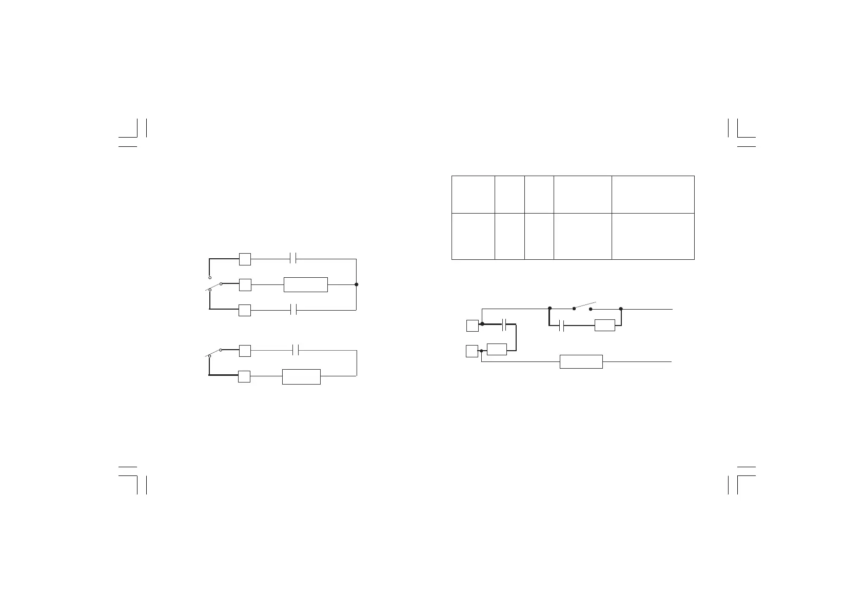
Switching inductive loads, high voltage transients may occur.
These transients may damage the internal contacts, PCB or affect
the performance of the instrument. In this care an external snubber
network should be connected across the terminals as near as
possible to the terminals (see Fig. 2.13).
Fig. 2.13 EXTERNAL PROTECTION FOR INDUCTIVE LOAD
GREATER THAN 40 mA AC
The value of capacitor (C) and resistor (R) are shown in the following
table.
C
C
C
C
NC
R
NO
C
NC
R
The same problem may occur when a switch is used in series with
the internal contacts as shown in Fig. 2.14
Fig. 2.14
In this case it should be better to protect the switch also as shown in
Fig. 2.14. Anyway the cable involved in relay output wiring must be
as far away as possible from input or communication cables.
LOAD
CURRENT
< 40 mA
< 150 mA
< 0.5 A
C
(µF)
0.0022
0.1
0.33
R
(Ω)
100
22
47
RESISTOR
POWER (W)
1/2
2
2
RESIST. AND
CAPAC. VOLTAGE
260 VA.C.
260 VA.C.
260 VA.C.
C
R
LOAD
R
C
POWER
LINE