43
SECTION 5 INSTRUMENT CALIBRATION PROCEDURES
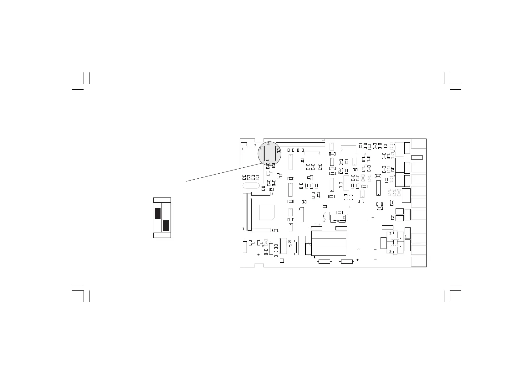
5.1 DIP SWITCHES LOCATION
To start with the calibration procedure, the internal
DIP SWITCHES , mounted on CPU card, must be
positioned as shown at left:
NOTE: during calibration procedure the serial
communication interface will be disabled.
Fig. 5.1
SW1 = ON
SW2 = OFF
ON
2
1