50
C 8 - RTD INPUT MINIMUM RANGE VALUE
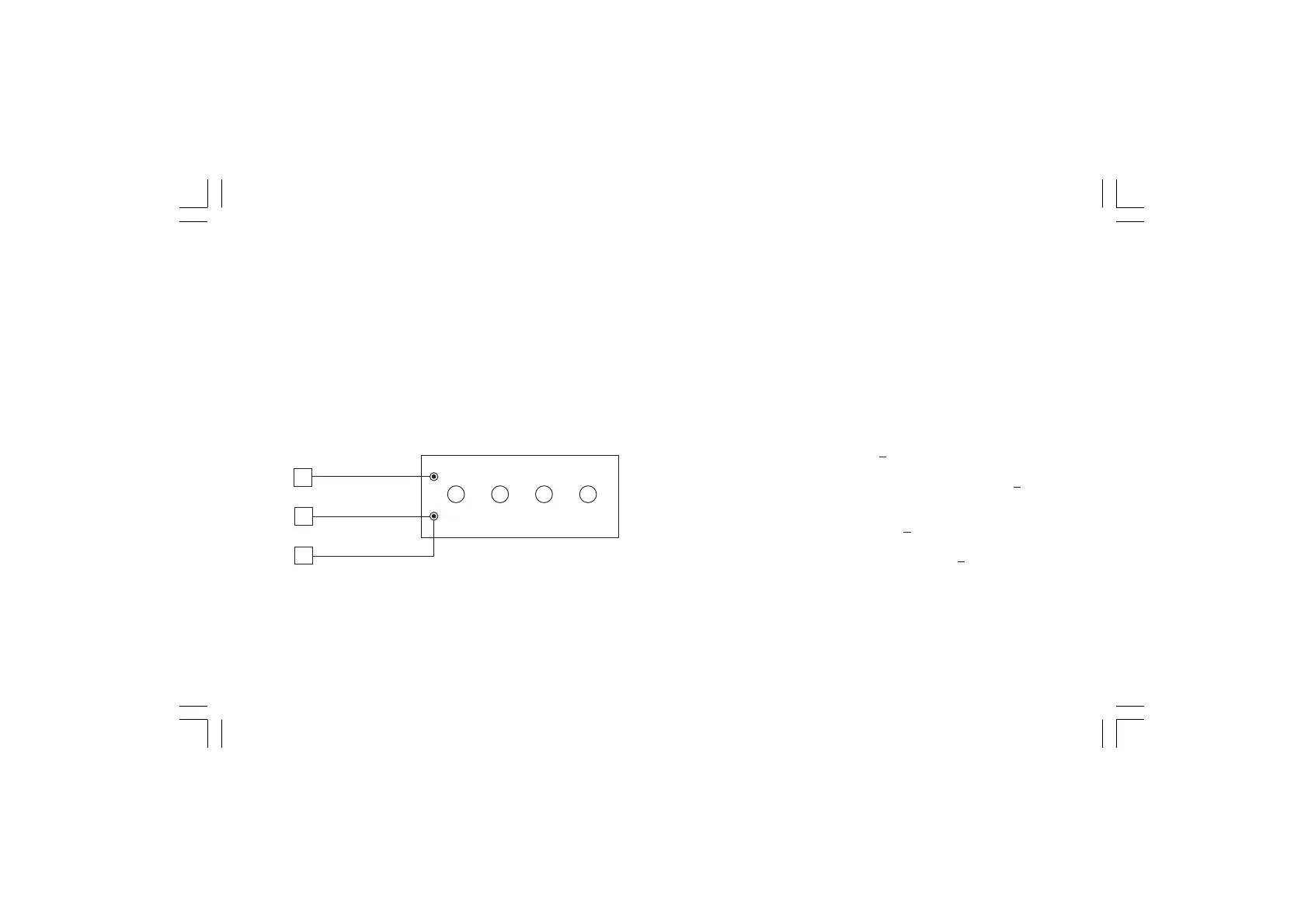
a) Connect a resistor box as shown in Fig. 5.6.
b) Set 0.00 Ω on the resistor box.
c) Push ▲ pushbutton, then the instrument will show "ON" and
"C 8".
d) After few seconds, start calibration routine by pushing F pushbut-
ton. The decimal point of least significant digit on the numerical
display will light to indicate that the instrument is performing
calibration. Then the displays will show "OFF" and "C 9".
Fig. 5.6
C 9 - RTD INPUT MAXIMUM RANGE VALUE
a)Set the resistance box to 500.00 Ω (see Fig. 5.6).
b)Push ▲ pushbutton, the displays will show "ON" and "C 9".
c) Wait few seconds then push F pushbutton.
d)The numerical displays will blank temporarily to show that the
instrument is performing the calibration routine.
RTD INPUT CHECK
a) The display will show "25000 Ω"
+10 counts otherwise set the
resistance box to 500.00 Ω (see Fig. 5.6)
The C9 calibration is correct if the indication is "25000Ω" + 10
counts.
b) Check the zero calibration by setting 0.00 Ω on the resistance
box; the readout must be "00000 Ω "
+10 counts.
To check the half scale linearity, set the resistance box to
250.00Ω and the readout should be "12500 Ω" +10 counts.
c) Push F pushbutton to proceed to next calibration step.
3
4
1