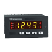
9
1.3.2 ANALOG RETRANSMISSION
Isolated analog retransmission of the displayed value.
Scaling: programmable between -1999 and 9999
Output type: 1) 0-20 mA or 4-20 mA, max. load 500 Ω, optoisolated
2) 0-10 V, minimum load 5000 Ω, optoisolated
Selection: between 0-20 mA, 4-20 mA and 0-10 V by internal jumper
and frontal keyboard.
Resolution : max. 0.1 % of the output span.
Accuracy: 0.2 % of the output span (@ 25°C).
Temperature drift: < 100 ppm/°C.
Digital filter: it is possible to set a digital filter on the retransmitted
value with a time constant equal to the time constant selected for the
readout value.
NOTE: The analog retransmission excludes the serial interface op-
tion.
1.3.3 AUXILIARY POWER SUPPLY
Isolation: galvanically isolated from instrument input and output.
Voltage output: 5, 10, 12 or 24 V DC selectable by jumpers.
Accuracy :
+ 5 %
Max. power: 0.5 W
1.4 CODING
MODEL
DPS = Digital panel indicator
POWER SUPPLY
3 = 100 to 240 V AC
5 = 24 V AC/DC
INPUTS
9 = TC, mV, V, mA, RTD
ALARMS
1 = 2 alarms
OPTIONS
1 = Auxiliary power supply
2 = Analog retransmission (mA) + auxiliary
power supply
3 = RS-485 + Auxiliary power supply
4 = RS-485
5 = Analog retransmission (mA)
DPS _ 9 1 1 _ 0 0