31
3.2.2 CONFIGURATION PROCEDURE
Once the internal dip switches have been positioned as described
in Fig. 3.1 proceed as follows:
1. The display will show "COnF"
NOTE: at this point it is possible to start the default parameter
loading procedure as detailed at section 6
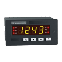
2. Push F pushbutton. The instrument shows the first parameter
code and the relative value.
3. To modify this value push ▲ or ▼ to obtain the desired setting.
When the display shows the new desired setting, push F pushbut-
ton to store the value and go to the next parameter.
It is possible to go back in the parameter sequence by using R
pushbutton but, after parameters modification, push the F pushbut-
ton otherwise the new value will not be stored (the storage is made
only when the F pushbutton is depressed).
3.2.3 PARAMETERS LIST
The following is the complete parameters sequence.
Some parameters may not be shown according to the previous
parameters setting.
1) POWER SUPPLY FREQUENCY
The display will show "LInE" followed by:
50 = 50 Hz
60 = 60 Hz
Push ▲ or ▼ pushbuttons to set the required frequency value.
Push the F pushbutton to memorize the new choice and go to the
next parameter.
2) INPUT TYPE
The display will show "InP." followed by:
TC = thermocouple input (go to step 3)
RT = RTD input (go to step 3a)
Ln = linear input (go to step 4)
Fr = Frequency input (NOT TO BE USE)
Push ▲ or ▼ pushbuttons to set the required input type.
Push the F pushbutton to memorize the new choice and go to the
next parameter.
NOTE: the input type selection shell be in accordance to the
instrument type (see CODING at para. 1.4).