14
B) INPUTS
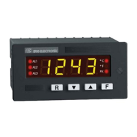
Fig. 2.4 THERMOCOUPLE INPUT WIRING
NOTE: Don’t run input wires together with power cables.
Use proper compensating cable preferably shielded (see
Table 1).
If shielded cable is used, the shield must be grounded at one
point only.
Pay attention to the line resistance; a high line resistance
may cause measurement errors (see PRODUCT SPECIFI-
CATIONS).
1 3
1 3
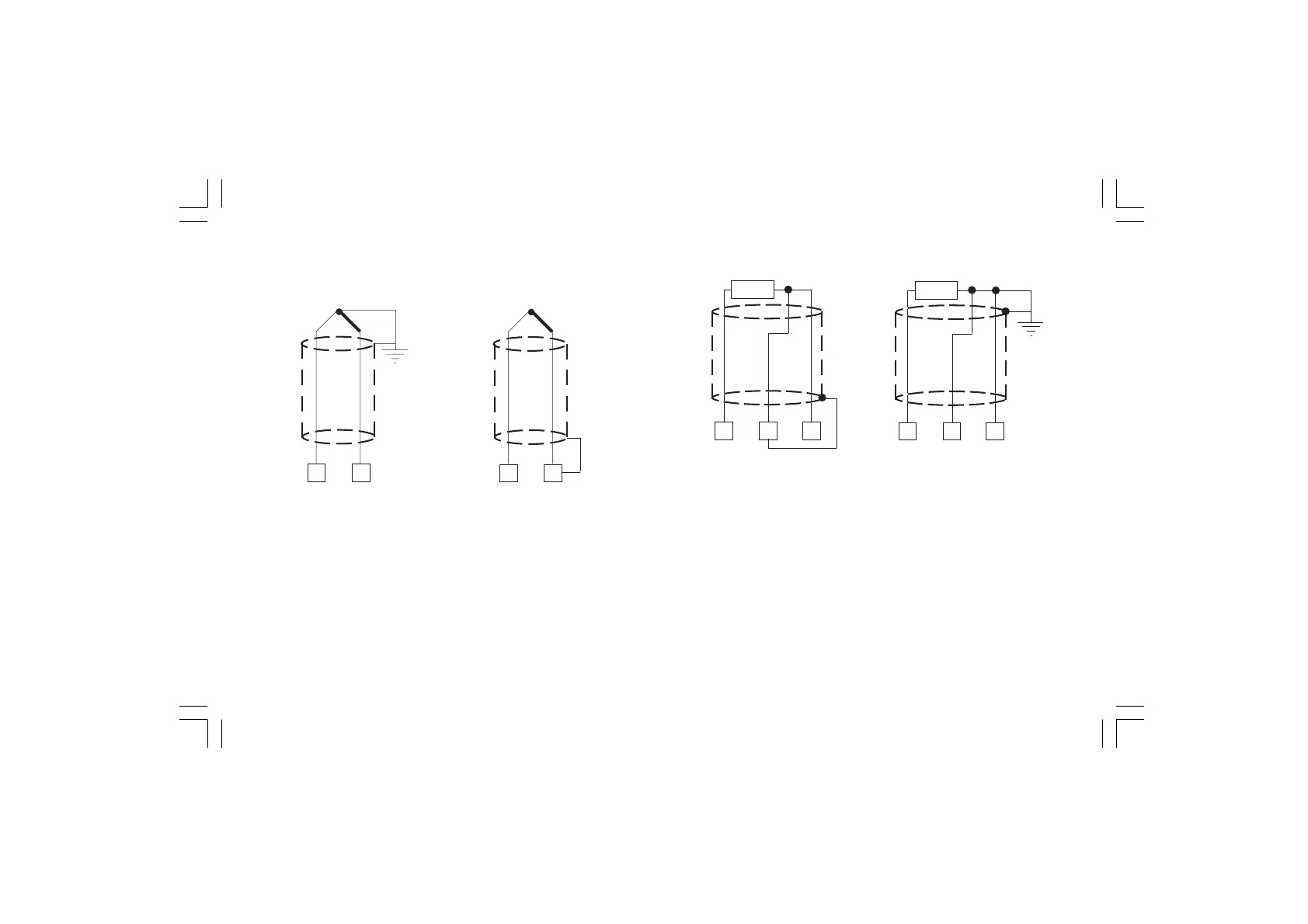
Fig. 2.5 RTD INPUT WIRING
NOTE: Don’t run RTD wires together with power cables.
If shielded cable is used, the shield must be grounded at one
point only.
Use copper wires with appropriate size (see "PRODUCT
SPECIFICATIONS").
The resistance of the 3 wires must be the same.
Any external components (like zener barriers etc..) connected
between sensor and input terminals may cause errors in measure-
ment due to excessive and/or not balanced line resistance or
possible leakage currents.
1 3
4
1 3
4