13
2.2 WIRING GUIDE LINES
Connections are to be made with the instrument housing installed in
its proper location.
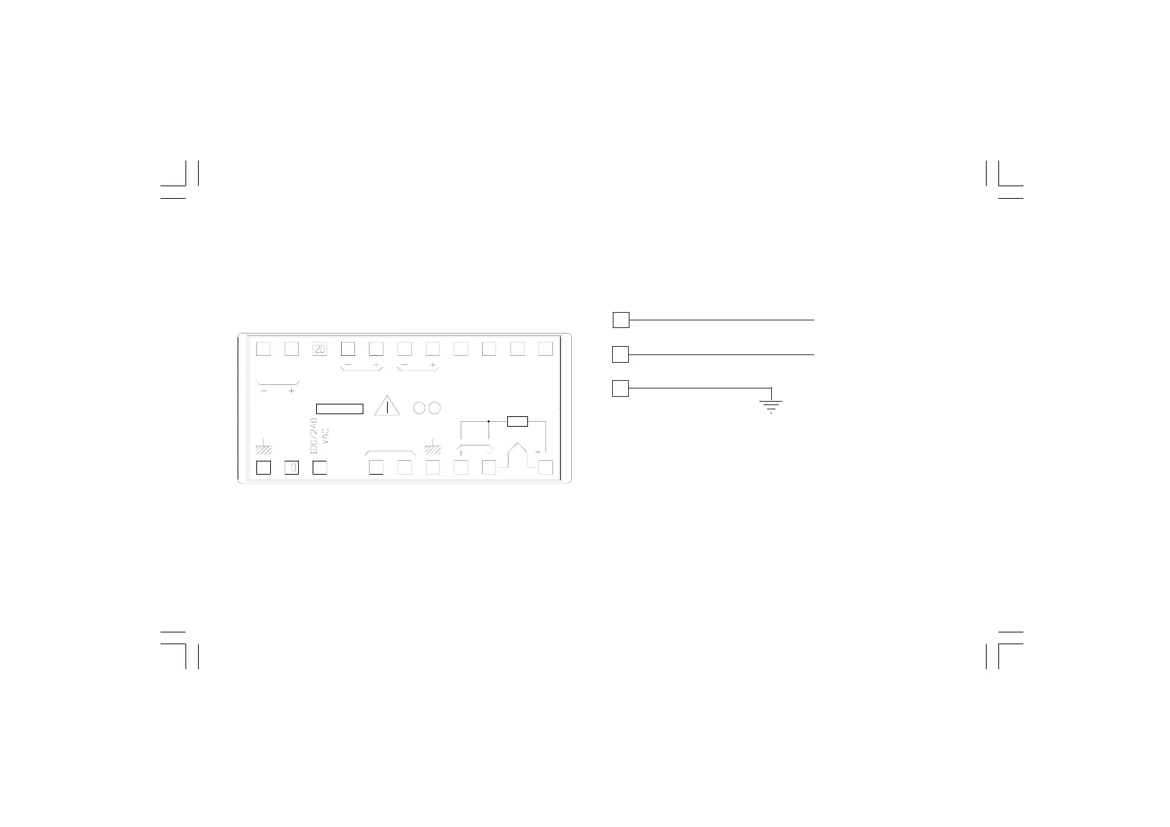
Fig. 2.2 REAR TERMINAL
A) POWER LINE
Fig. 2.3 POWER LINE WIRING
NOTE: 1) Before connecting the instrument to the power supply,
make sure that line voltage corresponds to lateral label
indication.
2) Terminal 11 must be connected to earth.
3) To avoid electric shock, connect power supply at the end
of the wiring procedure only.
4) The power supply input has no fuse protection.
Please, provide it externally.
9
10
11
100 V to 120 V AC
or 24 V AC/DC
LINE NEUTRAL
EARTH PWS
1
T/C
345679
1213141516171921
RTD
22
11
18
LOGIC
1
mV
mA/V
INPUT
AL2C
AL2
B/B'
A/A'
C/C'
AL1
AL1C
mA
V
REMOTE
VDC
SUPPLY
M0248-01
LN