Manual 0560956430 201 TORCH DATA 100i-400i
Aluminum
400A
N₂ Plasma / H₂O Shield
Flow Rates
N₂ (SLPM / SCFH) H₂O (GPH / LPH)
Preow
22 / 47 8 / 30
Culow 72 / 153 8 / 30
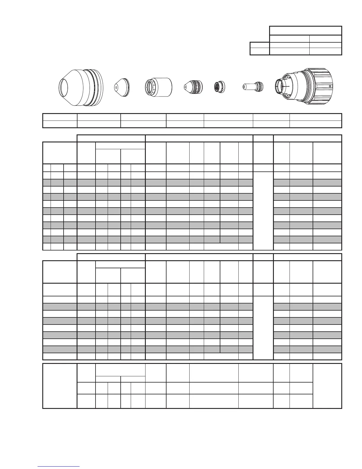
This Art Is For Reference Only
Shield Cup
Shield Cap
Shield Gas
Distributor
Tip
Gas
Distributor
Electrode
Cartridge Assembly
Art# A-10445
Shield Cup Shield Cap Shield Gas Distributor Tip Plasma Gas Distributor Electrode Cartridge
0559211401 0559210156 0559210084 0559210132 0559210063 0559210113 0559211400
Manual Gas Control Advanced Torch Height Control (THC) Basic THC CNC Control
Material
Thickness
Pre Flow
Pressure
(N2)
Cut Flow Rates / Pressures
Arc
Voltage
Cut Height
THC
Pierce
Delay
Pierce
Ignion
Height
Elevaon
Height
Control
Delay
Pierce
Height
without
Elevaon
Travel
Speed
CNC
Moon
Delay
Max Kerf Width
@ Rec. Speed
Plasma (N₂) Shield (H₂O)
ga (in) inch (psi) Ball (psi) Ball (psi)* (Volts) (in) ±0.005 (sec) (in) (in) (sec) (in) (ipm) (sec) (in)
- 1/2 0.500 17 150 119 8 NA 168 0.250 0.3 0.350 0.450 0.2
Not Recommended without
Elevaon Height
140 0.2 0.185
- 5/8 0.625 17 150 119 8 NA 177 0.300 0.7 0.450 0.550 0.2 110 0.5 0.195
- 3/4 0.750 17 150 119 8 NA 180 0.350 0.8 0.450 0.550 0.2 90 0.6 0.195
- 7/8 0.875 17 150 119 8 NA 180 0.350 0.9 0.450 0.550 0.2 75 0.7 0.215
- 1 1.000 17 150 119 8 NA 182 0.350 1.2 0.450 0.550 0.2 70 0.9 0.215
- 1 1/4 1.250 17 150 119 8 NA 190 0.350 1.4 0.450 0.550 0.2 65 1.0 0.215
- 1 1/2 1.500 17 150 119 8 NA 191 0.350 1.6 0.450 0.550 0.2 55 1.2 0.215
- 1 3/4 1.750 17 150 119 8 NA 200 0.420 1.8 0.500 0.600 0.2 40 1.4 0.240
- 2 2.000 17 150 119 8 NA 211 0.420 2.5 0.500 0.600 0.2 30 1.9 0.295
- 2 1/4 2.250 17 150 119 8 NA 215 0.420 4.8 0.500 0.600 0.2 20 2.2 0.320
- 2 1/2 2.500 17 150 119 8 NA 222 0.420 3.0 Edge Start 0.2 12 3.0 0.335
Manual Gas Control Advanced Torch Height Control (THC) Basic THC CNC Control
Material
Thickness
Pre Flow
Pressure
(N2)
Cut Flow Rates / Pressures
Arc
Voltage
Cut Height
THC
Pierce
Delay
Pierce
Ignion
Height
Elevaon
Height
Control
Delay
Pierce
Height
without
Elevaon
Travel
Speed
CNC
Moon
Delay
Max Kerf Width
@ Rec. Speed
Plasma (N₂) Shield (H₂O)
(mm) (Bar) Ball (Bar) Ball (Bar)* (Volts) (mm) ±0.1 (sec) (mm) (mm) (sec) (mm)
(mm/
min)
(sec) (mm)
12 1.2 150 8.2 8 NA 166 6.1 0.2 8.3 10.9 0.2
Not Recommended without
Elevaon Height
3720 0.1 4.6
15 1.2 150 8.2 8 NA 175 7.3 0.6 10.7 13.3 0.2 3000 0.4 4.9
20 1.2 150 8.2 8 NA 180 8.9 0.8 11.4 14.0 0.2 2170 0.6 5.1
25 1.2 150 8.2 8 NA 182 8.9 1.2 11.4 14.0 0.2 1790 0.9 5.5
30 1.2 150 8.2 8 NA 188 8.9 1.3 11.4 14.0 0.2 1690 1.0 5.5
35 1.2 150 8.2 8 NA 191 8.9 1.5 11.4 14.0 0.2 1520 1.1 5.5
40 1.2 150 8.2 8 NA 194 9.4 1.7 11.8 14.4 0.2 1280 1.3 5.7
50 1.2 150 8.2 8 NA 210 10.7 2.4 12.7 15.2 0.2 790 1.8 7.3
60 1.2 150 8.2 8 NA 218 10.7 4.0 Edge Start 0.2 420 2.6 8.3
Marking
Pre Flow
Pressure
(N₂)
Marking Flow Rates /
Pressures
Arc Voltage
Marking
Height
Pierce Ignion Height
THC and CNC
Delay
Control
Delay
Travel
Speed
Marking quality
degrades as
thickness
decreases.
45A Arc Current
Plasma (N₂) Shield (N₂)
Burn-through
may happen for
thicknesses <
1/16” (0.063”) /
1.6mm.
(psi) /
(Bar)
Ball
(psi) /
(Bar)
Ball
(psi) /
(Bar)
(Volts)
(in) ±0.005 /
(mm) ±0.1
(in) ±0.005 / (mm) ±0.1 (sec) (sec)
(ipm) /
(mm/ min)
15 / 1.0 80
60 /
4.1
NA
90 /
6.2
105 0.180 / 4.6 0.180 / 4.6 0 0 200 / 5080
BOLD TYPE indicates maximum piercing parameters. BOLD ITALIC indicates edge starts only.
BOLD TYPE indicates maximum piercing parameters.
* Pressure of the water supply line should be regulated by customer pressure regulator.
Note1: Ohmic height sensing is not recommended with water shield. Water on the plate interferes electrically with the ohmic sensing circuit.
Note2: Water source used for shield must be demineralized.
 Loading...