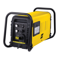
ESAB CUTMASTER 120
Manual 0-5380 INSTALLATION
3-1
SECTION 3 SYSTEM:
INSTALLATION
3.01 Unpacking
1. Use the packing lists to identify and account for each item.
2. Inspect each item for possible shipping damage. If dam-
age is evident, contact your distributor and / or shipping
company before proceeding with the installation.
3. Record Power Supply and Torch model and serial numbers,
purchase date and vendor name, in the information block
at the front of this manual.
3.02 Lifting Options
The Power Supply includes a handle for hand lifting only. Be
sure unit is lifted and transported safely and securely.
WARNING
Do not touch live electrical parts.
Disconnect input power cord before moving
unit.
!
WARNING
FALLING EQUIPMENT can cause serious per-
sonal injury and can damage equipment.
HANDLE is not for mechanical lifting.
• Onlypersonsofadequatephysicalstrengthshouldliftthe
unit.
• Liftunitbythehandles,usingtwohands.Donotusestraps
for lifting.
• Useoptionalcartorsimilardeviceofadequatecapacityto
move unit.
• Placeunitonaproperskidandsecureinplacebeforetrans-
porting with a fork lift or other vehicle.
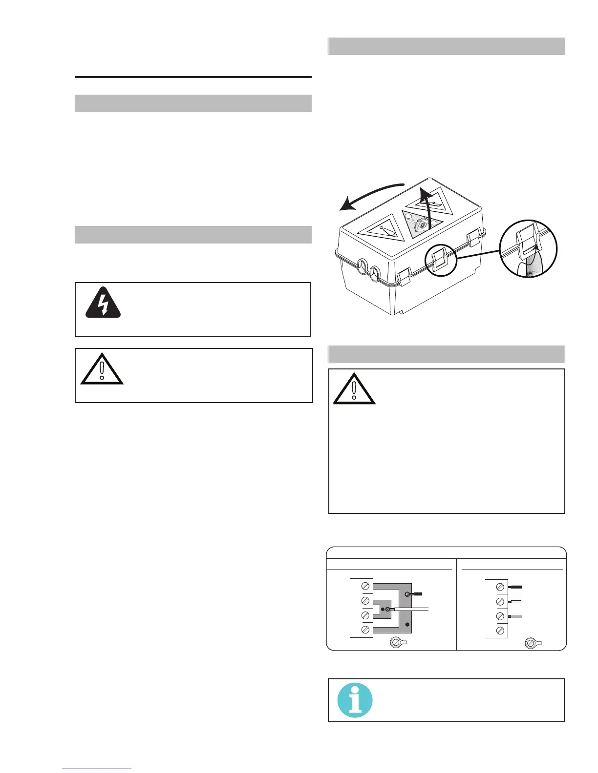
3.03 Opening the Contactor Cover
The input power cord is connected to the main contactor, the
contactor is located inside a box with a snap on cover. The cover
is held in place with two or more snap lock tabs. To remove the
cover release the front latch and tilt the cover up about ½ inch.
Then squeeze both sides of the cover and lift it straight up. See the
Primary Input Power Connections section for the necessary changes
to the Contactor. Remember to replace the Contactor Cover when
the changes are complete.
Art# A-11478
1
2
2
1
Contactor cover
3.04 Primary Input Power Connections
!
CAUTION
Check your power source for correct volt-
age before plugging in or connecting the
unit. Check the Voltage Selector at the rear
of the unit for correct setting before plug-
ging in or connecting the unit. The primary
power source, fuse, and any extension
cords used must conform to local electrical
code and the recommended circuit protec-
tion and wiring requirements as specified in
Section 2.
The following illustration and directions are for changing phase of
the power supply.
Art # A-08493
Input Power Cable Connections
Three-Phase (3ø)
Store copper jumpers on base plate
Single-Phase (1ø) and Jumper Settings
GND
L1
L2
L3
L4
GND
L1
L2
L3
L4
Single and Three Phase Input Power Wiring
NOTE!
There are two jumpers used for the single
phase 230V setting and none for three phase.